Table of Contents
Advertisement
Advertisement
Table of Contents

Related Manuals for CEFLA MyRay Hyperion X9


Summary of Contents for CEFLA MyRay Hyperion X9
- Page 1 97050543 Rev. 17 2018-12...
- Page 2 ITALIANO OPERATOR'S MANUAL...
-
Page 3: Table Of Contents
Contents 1. INTRODUCTION AND INDICATIONS FOR USE ..................... 5 1.1. DESCRIPTION OF THE MANUAL ........................6 1.2. GENERAL WARNINGS ............................6 1.3. REQUIREMENTS (NOT PROVIDED WITH THE PRODUCT) ................7 1.4. STANDARDS AND REGULATIONS ........................7 1.5. CLASSIFICATIONS .............................. 8 1.6. - Page 4 5.5. ACQUISITION OF THE EXAM ........................... 46 6. 3D TOMOGRAPHIC EXAMINATION (CBCT) ......................47 6.1. SELECTING THE EXAMINATION FROM THE CONTROL CONSOLE ............47 6.2. POSITIONING THE PATIENT FOR 3D EXAMINATIONS ................. 50 6.3. PERFORMING THE EXAMINATION ......................... 50 7. VIEWING AND SAVING ............................51 7.1.
-
Page 5: Introduction And Indications For Use
1. INTRODUCTION AND INDICATIONS FOR USE hyperion X9 is an extraoral X-ray system for digital panoramic exams, tele-X-rays and tomographies, intended to: (I) produce orthopanoramic images of the maxillofacial region and carry out diagnostic examination on teeth, dental arches and other structures in the oral cavity; (II) produce X-ray images of dental arches, cranium parts, carpus, and cephalometric examinations, if equipped with tele-X-ray arm (CEPH);... -
Page 6: Description Of The Manual
The original text of this manual is in Italian. 1.2. GENERAL WARNINGS The digital X-ray system with its drivers and software have been developed and manufactured by CEFLA s.c. - Via Selice Prov.le 23/A 40026 Imola (Italia), hereinafter referred to as the Manufacturer, which is the manufacturer and distributor in compliance with the EC Medical Device Directive. -
Page 7: Requirements (Not Provided With The Product)
Please pay particular attention to the sections in the manual where the following symbols appear: Patient or operator safety-related warnings. Important information on product use. For 3D machines only. In accordance with the privacy laws in force in several countries, all sensitive personal information must be adequately protected. -
Page 8: Classifications
The system is classified as a Class IIB medical electrical X-ray device in accordance with Medical Device Directive 93/42/EEC and subsequent amendments. 1.6. STYLISTIC CONVENTIONS The following symbols may be found on the X-ray device and in the Manual: CEFLA s.c.– via Selice Provinciale Name of the Manufacturer and place of production. -
Page 9: General Safety Warnings
POWER Power switch. Product/equipment identification code. Unit ON. Unit OFF. Ukraine compliance mark. 1.7. GENERAL SAFETY WARNINGS These instructions describe how to use the system correctly. Please carefully read this manual before using the device. The owner or the installation site manager is obliged to verify compliance with the local regulations in force and/or ask a Qualified Expert for advice. -
Page 10: Conditions Of Use
In case of claims or need of technical assistance, users in Brazil are required to contact the following email address: servico.odontologico@cefla.it. Users in the USA market are required to contact: Cefla North America Inc., 6125 Harris Technology Blvd., Charlotte, NC, 28269 United States Phone: +1 704 598 0020, e-mail: info@ceflaamerica.com 1.7.3. -
Page 11: Maintenance And Disposal
1.7.4. MAINTENANCE AND DISPOSAL Never remove the device covers. The device does not contain parts that can be repaired directly by the user. In the event of malfunctioning, do not attempt to carry out any type of maintenance operation. If you find or suspect any kind of system malfunctioning, do not attempt to carry out any type of maintenance operation and do not use the system on a patient, but directly contact your local distributor. -
Page 12: Cleaning And Disinfection
It is recommended to use the specific medium-level disinfectant, STER 1 PLUS (CEFLA S.C.), which is compatible with the painted surfaces, plastic parts and unpainted metal surfaces. Alternatively, it is recommended to use products that contain: 96% ethanol Concentration: maximum 30 g for every 100 g of disinfectant. -
Page 13: Hygiene Procedures For Patient Protection
(e.g. FDA, CE). Always replace the single-use hygienic protections of the bite piece before positioning a new patient. The single-use hygienic protections (Cefla code 97901337) must be stored in a dry and clean place without direct exposure to sunlight or UV rays. -
Page 14: Safety During X-Ray Device Movements
Do not use electronic equipment not compliant with IEC 60601-1-2 in proximity of life support equipment (e.g. pacemakers or heart stimulators) and hearing aids. Before using any electronic device in health facilities, always check that it is compatible with the other equipment present. The X-ray tube contains insulating mineral oil. -
Page 15: Emergency Button
1.8.4. EMERGENCY BUTTON The system is equipped with an emergency button to stop X-ray device operation, located under the patient support arm in proximity of the telescopic column. A remote emergency button is connected using the dedicated connector on the board located at the feet of the lifting column. 1 - Emergency button These buttons must be activated in the event of danger and emergency, for example, failed interruption of radiation from the source, in situations of evident danger to persons or when an emergency is signalled. -
Page 16: Electromagnetic Safety
1.8.8. ELECTROMAGNETIC SAFETY The device is intended for use in environments recognised as professional health facilities, as described in IEC 60601-1-2:2014. The device belongs to CISPR 11 Class A Group 1 and complies with immunity test levels specified by IEC 60601-1-2:2014 for professional health facilities. Before using any electronic device in health facilities, always check that it is compatible with the other equipment present. - Page 17 Guidance and Manufacturer's declaration - Electromagnetic emissions hyperion X9 is designed to operate in the specified electromagnetic environment. The customer or the user of hyperion X9 must ensure its use in an electromagnetic environment with the following features: Emission test Conformity Electromagnetic Environment hyperion X9 uses RF energy only for its internal...
- Page 18 Guidance and Manufacturer's declaration - Electromagnetic immunity hyperion X9 is designed to operate in the specified electromagnetic environment. The customer or user of hyperion X9 must ensure that it is used in such environment. Immunity test IEC 60601-1-2 Level of Electromagnetic Environment Test level conformity...
-
Page 19: Protection Against Radiation
1.8.9. PROTECTION AGAINST RADIATION This system is an X-ray equipment. As such, it exposes patients and operators to risks from radiation. It must be used in compliance with the safety standards set forth by the radiological protection regulation in force in the country of use. Following are some of the provisions: Control the emission of X-rays exclusively from the control workstation, the exam room must be suitably shielded (if required by the local regulations in force). -
Page 20: Stray Radiations
1.8.11. STRAY RADIATIONS Leaked radiation measurement is highly influenced by ambient conditions, such as wall composition and positioning, therefore, under certain circumstances, the detected values can be significantly different. The measurement points used are at 0.5 m, 1.0 m and 2.0 m, respectively, from a central rotation axis. The circular measurement points are determined based on the patient bite position on the machine. -
Page 21: Description Of Operation
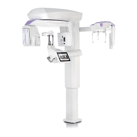
2. DESCRIPTION OF OPERATION The X-ray device consists of a rotary arm fitted on a column support for carrying out panoramic X-rays or tomographic examinations. The rotary arm features roto-translation motorised movements which allow moving X-ray emission system and image detector around the patient, according to complex orbits following the morphological profile. -
Page 22: Components
3. COMPONENTS Basic machine Sensor for panoramic images Optional, arm for tele-X-rays Craniostat Optional, sensor for tele-X-rays (also used for panoramic X-rays) CBCT detector Optional, standard stand Optional, “easy access” stand Remote X-ray button USB Pen Drive including Instruction Manual, Drivers and Software for image display. The multiple-workstation hardware key allowing to use the 3D functions and/or the DICOM licenses is optional in the 2D version, while it is always included in the 3D version. - Page 23 Support for 3D scans of models, impressions, X-ray templates, phantoms for quality checks / consistency tests (optional) Phantom for 2D quality checks (optional) Phantom for 3D quality checks (optional) 22" / 24" medical monitor for image displaying (optional) 2D or 3D image acquisition workstation (optional) Multiple-workstation hardware keys for the activation of additional licenses (1, 5, 10, 25, 50, 250) on LAN network (optional) OPERATOR'S MANUAL...
-
Page 24: Control Panel
4. CONTROL PANEL 4.1. CONSOLE ONBOARD THE MACHINE Control panel area Button Description and use Confirmation Button Column Upward Movement Column Downward Movement Craniostat movement (up) + (only in system equipped with CBCT) Craniostat movement (down) – (only in system equipped with CBCT) Canine cusp or condyle Vertical Laser positioning to frame the patient (+) Canine cusp or condyle Vertical Laser positioning to frame... -
Page 25: X-Ray Emission Remote Control
4.3. X-RAY EMISSION REMOTE CONTROL The system is equipped with a remote control to enable X-ray emission. The remote control has: 1) A button to confirm X-ray emission 2) Two LEDs Green (device ready for emission) Yellow (emission in progress) When the system is ready (green LED on fixed), you can start X-ray emission by pressing the button on the remote control and holding it down for the entire duration of the examination. -
Page 26: Performing A 2D X-Ray Examination
5. PERFORMING A 2D X-RAY EXAMINATION The steps to follow to properly perform a 2D X-ray examination are: 1 – Turn on the system 2 – Select the X-ray examination on the touch screen display 3 – Prepare the X-ray examination 4 –... - Page 27 Dentition examinations (DENT): Preview Name Description BITEWING Set of 4 optimised images for representation of the crowns of the Scanning time: entire dentition. 12.9 s Magnification 1.43 RH BITEWING Set of 2 optimised images for representation of the crowns of the Scanning time: right dentition.
- Page 28 Temporomandibular joint examinations (ATM): Preview Name Description DOUBLE R-L Executes both the lateral examination (Magnification 1.30) and Scanning time: the frontal examination (Magnification 1.50) of both the left and 12.8 s the right joints; in total four images. FRONTAL R-L Posteroanterior projection of both joints.
-
Page 29: Selecting An Examination
Teleradiographic examinations (CEPH): Preview Name Description ANTERO-POST Anteroposterior (AP) or posteroanterior (PA) examination of Scanning time the cranium (Length 20 cm). 6.6 s Magnification 1.11 SUB-CHIN VX Submentovertex examination of the cranium (length 20cm), Scanning time including reverse Waters e Towne projections. 10.0 s Magnification 1.11 LATERO-LAT... -
Page 30: Setting An Examination For Children
5.2.3. SETTING AN EXAMINATION FOR CHILDREN To activate the examination parameters adapted to the build of a child, tap the CHILD icon , if available. The icon is highlighted if the settings for children are active and goes back to the initial state when they are deactivated by tapping on the icon again. -
Page 31: Setting The Projection Type
5.2.5. SETTING THE PROJECTION TYPE In some examination categories, different projection types are available. In the PAN and TMJ categories, tapping the icon , you can switch between one type of projection and the next. For the panoramic X-rays, you can choose between HD and QUICK. PAN HD PAN QUICK The DTS function is not available for the PAN QUICK protocol. -
Page 32: Selecting A Reduced Anatomic Region
CEPH For the teleradiographic examinations you can choose between LATERAL and FRONTAL projections. The icon changes status as shown CEPH FRONTAL CEPH LATERAL For ceph lateral examinations, it is possible to enable the shoulder anti-collision option if the patient anatomy requires The icon changes status as shown: (option enabled) (option disabled) -
Page 33: Configuration Of The X-Ray Technique Factors
5.2.7. CONFIGURATION OF THE X-RAY TECHNIQUE FACTORS On the EXAMINATION page, tapping the icon can access CONFIGURATION of the X-ray technique factors (KV, mA, and seconds of exposure) according to the patient’s build. Configuration page. AUTOMATIC: the X-ray technique factor configuration ensures the best quality of the final image, while minimising the amount of X-rays received by the patient. -
Page 34: Preparation Of The X-Ray Examination
5.3. PREPARATION OF THE X-RAY EXAMINATION 5.3.1. DEVICES FOR PATIENT POSITIONING Examination type Movable support Image PAN DENT SIN Craniostat, chinrest and bite piece Subnasal support and craniostat CEPH Tele-X-ray cephalostat Remember to change the single-use protections before positioning each new patient. Before each X-ray examination, make sure that the patient has taken all metal objects off, such as glasses, removable prostheses, earrings and other removable metal objects at the level of the head or the neck. -
Page 35: Sensor Positioning
5.3.2. SENSOR POSITIONING Check that the sensor to be used is fitted in a suitable position for the examination to be performed, otherwise relocate it. If the sensor is not in a suitable position for the examination to be performed, a warning will appear on the control console onboard the machine and you will not be able to continue with the examination selected. -
Page 36: Patient Access Status - Minimum Wait Status
5.3.3. PATIENT ACCESS STATUS – MINIMUM WAIT STATUS When the X-ray device is ready, it may be in two distinct and consecutive conditions which you access by pressing the CONFIRM button Patient Access Status = the X-ray device sets up to allow patient access and correct cranium positioning. Minimum Wait Status = this is obtained when pressing the CONFIRM button again after positioning the patient;... -
Page 37: Examination Summary Page
5.3.4. EXAMINATION SUMMARY PAGE This page can be viewed only if the device is ready. This page shows: the various X-ray technique factors correctly set and an icon for the relevant setting mode (AUTOMATIC), (PRESET) or (CUSTOM); the examination type selected; icons at the bottom of the page with which you can redefine the projections and the anatomic region involved in the examination. -
Page 38: Patient Positioning
5.4. PATIENT POSITIONING Set the X-ray device to Patient Access Status before having the patient access and before starting any cranium positioning operation. If the X-ray device is not in Patient Access Status, press the CONFIRM button once, wait for the X-ray device to complete its movements and for the laser traces to turn on. -
Page 39: Patient Positioning Description (Craniostat)
5.4.2. PATIENT POSITIONING DESCRIPTION (CRANIOSTAT) Craniostat components: 1 – Base 2 – Rods 3 – Chinrest 4 – Bite piece 5 – Bite piece block lever 6 – Cross member 7 – Front support 8 – Arms 9 – Anatomic arches 10 –... -
Page 40: Craniostat Motor-Driven Support
5.4.3. CRANIOSTAT MOTOR-DRIVEN SUPPORT The chinrest is movable only for 3D examinations. Use the buttons located on the left-hand side of the control console to raise or lower the chinrest to suit the patient. Briefly pressing the button, moves the mechanism1 mm up or down, while holding it down moves it continuously at constant speed. - Page 41 If you are performing a BITEWINGS examination, you NEED TO ADJUST THE BITE PIECE TO A PRECISE HEIGHT. It is advisable to remove the chinrest. Then adjust the bite piece vertically, in the position where a clack is heard and a slight resistance to vertical sliding is perceived. After having reached this position, lock the bite piece as described in par.
-
Page 42: Tmj Examination
5.4.5. TMJ EXAMINATION 5.4.5.1. LATERAL TMJ 1) Remove the chin rest and the bite, and insert the under-nose support. 2) Adjust the unit height, in order to facilitate the patient’s access, using the keys to move the column upward or downward until the under-nose support reaches the height of the nose base. The telescopic column will move slowly at first, then it will speed up. -
Page 43: Frontal Tmj
6) Make sure that the examination required is correctly selected, observing CLOSED MOUTH OPEN MOUTH icon. Note, in case of examination with open mouth, the light trace translates forward: in fact, when the mouth is wide opened, the patient’s condyle comes out of the mandibular fossa and moves forward. -
Page 44: Teleradiographic (Ceph) Examinations
5.4.6. TELERADIOGRAPHIC (CEPH) EXAMINATIONS Teleradiographic examinations can be performed only if the system is equipped with a tele-X-ray arm with relative cephalostat. For these examinations the patient generally remains standing. For very tall or very short patients or in a wheelchair, the examinations may be performed with the patient sitting down. -
Page 45: Positioning For Dts Examination
5.4.7. POSITIONING FOR DTS EXAMINATION Carefully read the instructions provided at the beginning of paragraphs 5.4 and 5.4.1. The positioning devices to be used for this family of examinations are those specific for PAN/DENT/SIN, as indicated in paragraph 5.3.1. For patient positioning for PAN examinations, follow the instructions provided in paragraph 5.4.4. In case the volume reconstruction involves the rear side of the mandible (see figure 1), the patient must be positioned as shown in figure 3: The horizontal laser must pass through the auditory meatus and the base of the nose so that it is parallel with the mandible plane, whereas the vertical laser must always be positioned close to the upper canine. -
Page 46: Acquisition Of The Exam
5.5. ACQUISITION OF THE EXAM Visually check that the patient is correctly positioned and that the central green LED on the X-ray remote control is on fixed. Optionally, press the CONFIRM button to go to the Minimum Wait Status position. Ask the patient not to move during the examination and to breathe slowly and regularly. -
Page 47: D Tomographic Examination (Cbct)
6. 3D TOMOGRAPHIC EXAMINATION (CBCT) ONLY FOR 3D DEVICES The CBCT examination is obtained by three-dimensional reconstruction of the anatomic region X-rayed and can be consulted both through two-dimensional views and three-dimensional representations generated by a program run on a workstation (PC). Read the iRYS software user manual for the instructions for image processing. - Page 48 In both cases the adjacent screen will be displayed, showing the correctly selected CBCT program. 1) Choosing the field of view (FOV) Set the field of view (FOV) by pressing the icon The SET FOV screen is displayed: select the field of view to be used.
- Page 49 3) Select Mode Select the required examination mode: High resolution; total scanning time ~18s, with minimum voxel size 150µm. Maximum resolution; total scanning time ~36s, with minimum voxel size 75µm. 4) Selecting the volumetric reconstruction centre Select CBCT reconstruction centre from EXAMINATION screen by touching on the screen the anatomical area to be reconstructed.
-
Page 50: Positioning The Patient For 3D Examinations
6.2. POSITIONING THE PATIENT FOR 3D EXAMINATIONS 1) Once you have completed preparation of the X-ray device, have the patient access. 2) Adjust the height of the motor-driven column using the buttons to facilitate patient access. Bring the column up to the height of the patient. 3) The patient should grip the handles with both hands and be in an erect position. -
Page 51: Viewing And Saving
7. VIEWING AND SAVING In order to view and save the examination, you need a PC and dedicated software. The X-ray system is supplied with the iRYS program for viewing and saving the examinations. If you have this software, refer to the iRYS user manual. If you use third-party programs for viewing and saving the examinations, refer to the instructions provided with the software application used. -
Page 52: Control Console
A PNG image will be saved on the USB key, which needs to be dragged to iRYS in order to be viewed correctly. Listed below are the USB keys that have been tested for compatibility with the device: Sandisk Cruzer 4GB, Sandisk Cruzer 8GB, Sandisk Cruzer 16GB, Kingston Traveler 16GB,... -
Page 53: Touch Screen Display Icon
8.2. TOUCH SCREEN DISPLAY ICON Button Description and use Button Description and use FAVOURITES home screen HOME button CONSOLE CONFIGURATION menu pressing this icon, CONSOLE CONFIGURATION Current language selection menu can be accessed Touchscreen configuration menu Reset favourite list selection Calibration button Touchscreen button sensitivity Touch the centre of the blue... - Page 54 Button Description and use Button Description and use FAVOURITES button Allows adding current examination in the favourites list; CHILD SIZE button once this icon has been pressed, By pressing this button it is the position of the list in which the possible switch from...
- Page 55 Button Description and use Button Description and use Front Ceph Side Ceph Allows selecting the frontal tele- Press to select the side tele-X-ray X-ray examination mode examination mode Shoulder anti-collision option Shoulder anti-collision option disabled (default), for side Ceph enabled, side Ceph examinations.
-
Page 56: Periodic Checks And Maintenance
9. PERIODIC CHECKS AND MAINTENANCE In the interest of safety and health of patients, the staff or third parties, inspections and maintenance need to be carried out at scheduled intervals. Period Operator Object Description Yearly Specialised technician of The X-ray device as a In order to ensure the the dealer that initially whole... -
Page 57: Radiological Characteristics
10.2. RADIOLOGICAL CHARACTERISTICS Generator voltage 60 – 85 kV continuous mode (2D MODE) 90kV pulsed mode (3D CBCT MODE) (automatically or manually selectable in steps of 1 kV) Maximum continuous input anode power 42 W Anode current 4 – 10 mA automatically or manually selectable in steps of 1 mA Maximum deviations from declared values kV: <... -
Page 58: Radiological Features In Cbct Mode
Generator reference axis: 10.3. RADIOLOGICAL FEATURES IN CBCT MODE Operating voltage 90kV with all projections Generator voltage at maximum current 90kV - 10mA Load factors for the maximum output power 90kV - 10mA Maximum output rated power (value averaged with 810VA (90kV 10mA - 20/25% duty cycle) T>4s) Exposure time (CBCT) -
Page 59: Isodose Curves For Cbct Examinations
10.4. ISODOSE CURVES FOR CBCT EXAMINATIONS 10.5. ISODOSE CURVES FOR 2D EXAMINATIONS OPERATOR'S MANUAL... -
Page 60: Ctdi (Computed Tomography Dose Index) Measurements
10.6. CTDI (COMPUTED TOMOGRAPHY DOSE INDEX) MEASUREMENTS The CTDI was measured using a cylindrical PMMA phantom with a diameter of 16 cm with holes at 12, 3, 6 and 9 o’clock and in the centre. Diagram of PMMA cylinder for CTDI measurements During the measurements, the holes that remained empty were filled with PMMA cylinders and the ionisation chamber was inserted in the hollow reference cylinder. - Page 61 6.00 6.00 6.00 6.00 6.00 [11x5] exposure time (s) HiRes 54.00 54.00 54.00 54.00 54.00 CTDI100 [mGy] 7.748 6.647 6.944 6.468 6.607 4.00 4.00 4.00 4.00 4.00 [8x8] exposure time (s) 14.40 14.40 14.40 14.40 14.40 CTDI100 [mGy] 2.080 1.519 1.664 1.448 1.600...
-
Page 62: Cbct Detector Characteristics
10.7. CBCT DETECTOR CHARACTERISTICS Pixel size 127 x 127 µm Sensitive area dimensions 81x130, 130x130 mm (depending on the detector installed) Resolution 3.94 LP/mm 10.8. PANORAMIC SENSOR CHARACTERISTICS(PAN) Pixel size 48 x 48 µm Sensitive area dimensions 6 x 146 mm Resolution 5.2 LP/mm Primary screen... -
Page 63: Dimensional Characteristics
10.11. DIMENSIONAL CHARACTERISTICS Weight (basic machine) 180 Kg Weight (cephalometric unit) 25 Kg Maximum plan dimensions (basic machine) 1519 x 1312 mm Maximum plan dimensions (with cephalometric unit 1519 x 1829 mm installed) Height Min 1590 mm Max 2380 mm 10.12. -
Page 64: Pc Requirements
10.13. PC REQUIREMENTS For 3D machines only. CBCT acquisitions Requirements for PC workstation dedicated to CBCT primary reconstruction, directly connected to the X-ray acquisition device. CONFIGURATION CONFIGURATION CONFIGURATION CONFIGURATION COMPONENT 1 CPU INTEL XEON E3-1270 V3 1 CPU INTEL I7 1 CPU INTEL –... - Page 65 Win7 Win7 Win10 VIDEO CARD POWER SUPPLY 32 bit 64 bit 64 bit Sapphire Radeon R7 265 – DualX – 2GB GDDR5 ॰ ॰ ≥ 500W Sapphire Radeon R7 260X – OC – 2GB GDDR5 ॰ ॰ ≥ 500W Sapphire Radeon R7 250X – VaporX – 1GB/2GB GDDR5 ॰...
- Page 66 2D acquisitions Requirements for PC workstations dedicated to X-ray acquisitions in the case they or the device are dedicated only to two-dimensional examinations. Please find below the minimum requirements required. Characteristics lower than those specified could result in poor performance or impossible acquisition of X-ray examinations from this workstation.
-
Page 67: Identification Label Position
10.14. IDENTIFICATION LABEL POSITION PAN sensor nameplate Laser danger and warning nameplates CBCT sensor nameplate Generator nameplate CEPH arm nameplate CEPH sensor identification nameplate DHHS and WARNING nameplate Main nameplate Mark nameplate Plate images are purely illustrative; refer to the plate placed on the device. OPERATOR'S MANUAL... -
Page 68: Error Messages
11. ERROR MESSAGES Code Message Solution USER COMMUNICATIONS The shielded door connected to the Close the door or any other device to X-ray device is open make X-ray emission safe for the operator. WARNING X-ray Button released during Hold the X-ray emission button until exposure the end of the procedure. - Page 69 Code Message Solution 0.13 2D Detector failed to turn ON Check removable sensor’s contacts. Unplug the sensor and plug it back. 0.14 X-Ray Start-Command aborted 1) Check Converter board diagnostic LEDs (>15s). 2) Verify CAN connector (KCB1) on converter board. 0.16 Relocate Detector...
-
Page 70: User's Licence Contract
X-ray system, and to the image display and storage software altogether identified as “iRYS” and “iRYS viewer” (hereinafter referred to as “Software”) designed by CEFLA s.c. - Via Selice Prov.le 23/A 40026 Imola (Italia) (hereinafter referred to as ”Author”) and handed to the customer (hereinafter referred to as “User”). These conditions are understood fully recognised and accepted at the time of program installation. -
Page 71: Use Of The Software Product And Express Termination Clause
12.1.3. USE OF THE SOFTWARE PRODUCT AND EXPRESS TERMINATION CLAUSE a. Software. The User can install the Software and can use it under the conditions and within the limits established in this licence. The User is not authorised to distribute the Software, whether free-of-charge or upon payment, and cannot provide services or develop products or software applications based on the Image Software or which make use of it in any way whatsoever. -
Page 72: Written Form
12.1.7. WRITTEN FORM Any modifications should be made in written form. Failure to observe the above shall result in the agreement being made null and void. The parties agree not to recognise the validity in law of any verbal agreements made by any person previously, at the same time or subsequently to the written contract and state that at no time from this moment on shall any attempt be made to validate any verbal agreement which might alter that laid down in the present general conditions. -
Page 73: Inspection And Maintenance
13. INSPECTION AND MAINTENANCE 13.1. USER INSPECTION These instructions describe the maintenance procedures for the extraoral X-ray system. These instructions apply to all versions of said equipment, as well as all the accessories that may have been provided, therefore the description of some parts may not correspond to your equipment. Inspection and preventive maintenance must be performed at scheduled intervals to protect the health and safety of patients, users and other persons in accordance with national regulations regarding the use and maintenance of dental x-ray units that are in force in the country where the device is installed. -
Page 74: Technical Maintenance
13.2. TECHNICAL MAINTENANCE These instructions describe the maintenance procedures for the extraoral X-ray system. These instructions apply to all versions of said equipment. In order to ensure the operational safety and functional reliability of the equipment installed, at least once a year an authorized service technician must perform a full inspection of the device. When taking measurements that require a multimeter, always use a calibrated digital multimeter. - Page 75 Figure 1 Figure 2 OPERATOR'S MANUAL...
Need help?
Do you have a question about the MyRay Hyperion X9 and is the answer not in the manual?
Questions and answers