Table of Contents
Advertisement
Quick Links
TideMaster - Operating Manual
Document ID
MANUAL-1094978189-1 | issue 1.1
Date:
July 2021
This confidential document was prepared by the staff of Valeport Limited, the Company, and is the property
of the Company, which also owns the copyright therein. All rights conferred by the law of the copyright and
by virtue of international copyright conventions are reserved to the Company. This document must not be
copied, reprinted or reproduced in any material form, either wholly or in part, and the contents of this
document, and any method or technique available there from, must not be disclosed to any other person
whatsoever without the prior written consent of the Company.
© 2021 Valeport Ltd
Valeport Ltd
St Peter's Quay
Totnes TQ9 5EW
United Kingdom
As part of our policy of continuous development, we reserve the right to alter, without prior notice, all
specifications, designs, prices and conditions of supply for all our equipment
Phone:
+44 1803 869292
email:
sales@valeport.co.uk
Web:
www.valeport.co.uk
Advertisement
Table of Contents

Related Manuals for Valeport TideMaster


Summary of Contents for Valeport TideMaster
- Page 1 Date: July 2021 This confidential document was prepared by the staff of Valeport Limited, the Company, and is the property of the Company, which also owns the copyright therein. All rights conferred by the law of the copyright and by virtue of international copyright conventions are reserved to the Company. This document must not be...
-
Page 2: Table Of Contents
Pressure Sensor ......................10 2.4.2 VRS-20 Radar Level Sensor ..................10 3 Powering the Unit ..................11 Alkaline Battery Warning ..................11 To Turn the TideMaster On................. 11 3.2.1 Delayed Start ......................11 To Turn the TideMaster Off................. 11 Changing Batteries ..................... 12 Battery Life Scenarios .................. - Page 3 Contents 6 Set Up ....................... 19 Interrupting TideMaster ..................19 Set Up TideMaster Using the Control Panel ............19 6.2.1 Instrument Set Up ...................... 19 6.2.2 Sampling Set Up ......................21 6.2.3 Logging Set Up ......................21 6.2.4 Output Set Up ......................22 6.2.5...
- Page 4 10.4 METPAK II ......................52 10.5 MaxiMet ......................52 10.6 miniCT ........................ 53 10.7 3m Y Lead (RS232) .................... 53 11 Declaration of Conformity - TideMaster ........... 54 11.1 UKCA Certificate ....................54 11.2 EU CE Certificate ....................55 © 2021 – Valeport Ltd...
-
Page 5: Introduction
Express (PC software package). Both allow the TideMaster to be configured, calibrated and the recorded data to be extracted and visualised. The TideMaster can also run one additional sensor. The additional sensor will be run on the same sampling pattern as the tide sampling pattern. It can be specified with:... -
Page 6: Features
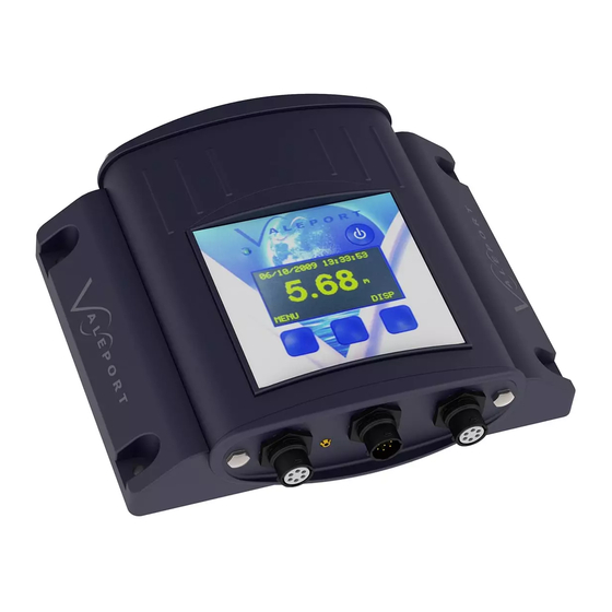
TideMaster - Operating Manual: MANUAL-1094978189-1 | issue: 1.1 1.2 Features TideMaster shown below with optional OLED control display panel. Non-Display model is identical other than the absence of the display and the lower three control buttons. © 2021 – Valeport Ltd... -
Page 7: Mounting Template
Minimum Range: 0.8 m Maximum Range: 20 m Beam Angle: ±6° Frequency: 25 GHz Accuracy: ±10 mm Precision: 1 mm Dimensions Length: 255mm Width: 130mm Height: 130mm (75mm without mount) Weight: ~2 kg © 2021 – Valeport Ltd Page | 3... - Page 8 TideMaster - Operating Manual: MANUAL-1094978189-1 | issue: 1.1 TideMaster - Logging Unit Housing: Injection molded housing, waterproof to IP67 (1m for 30 minutes) with injection molded mounting bracket. Display: Optional 128x64 OLED keypad display for configuration and data display. Internal Power: 4 "C"...
-
Page 9: Installation
A template for the mounting screws is supplied in Section 12. The TideMaster is fixed to the wall bracket with the use of the supplied metal T-bar. The TideMaster should be placed in the bracket and the metal bar slid into place from the top. The bar can be locked in place with the use of the supplied screw. -
Page 10: Shortening The Transducer Cable
TideMaster - Operating Manual: MANUAL-1094978189-1 | issue: 1.1 2.2.3 Shortening the Transducer Cable If a user wishes to shorten the signal cable, then this can be done, but care has to be taken in re-terminating the connector in order to ensure the integral vent tube is properly terminated in the connector. If the cable is shortened, the pressure calibration will alter slightly, but provided the site calibration is carried out, any variations caused by the shortening of the cable will be taken account of. -
Page 11: Boom Mounting
Section 2 | Installation 2.3.1 Boom Mounting The radar is supplied with a stainless-steel clamp (as pictured) for attaching to railings/scaffold poles © 2021 – Valeport Ltd Page | 7... -
Page 12: Direct Mounting
TideMaster - Operating Manual: MANUAL-1094978189-1 | issue: 1.1 See example of boom constructed from standard scaffolding parts and attached to existing railing structure 2.3.2 Direct Mounting The clamp can be removed and the stainless-steel adaptor plate fitted directly to a mounting surface if required. -
Page 13: Levelling
To insert the bare wires into the terminals, push in the orange tab in with a fine screwdriver and release to clamp the wire. The output from the junction box will depend on the configuration of the VRS-20. Refer to section Wiring Information © 2021 – Valeport Ltd Page | 9... -
Page 14: Calibration
2.4 Calibration 2.4.1 Pressure Sensor If the TideMaster is supplied with a pressure sensor, it will be shipped with a factory calibration, which provides an output of pressure in decibars and takes out any non-linearity in the transducer characteristic. Note that the pressure calibration is specifically for a combination of TideMaster and transducer, and the unit and transducer serial numbers are held in the logger memory. -
Page 15: Powering The Unit
3.2 To Turn the TideMaster On The TideMaster switches on when the power button on the top right of the front panel is pressed (quick press). The LED to the left of the panel will flash ten times in rapid succession to indicate the unit is initialising. -
Page 16: Changing Batteries
Remove any residual moisture from around the seal. Replace the 4 C cell batteries, taking care to insert them in the correct orientation. Take note of the orientation markings on the battery board. TideMaster will not operate if batteries are incorrectly installed Check the O-ring on the battery compartment lid for damage and debris. -
Page 17: Battery Life Scenarios
Section 3 | Powering the Unit 3.5 Battery Life Scenarios The standard alkaline cells in the TideMaster have a nominal capacity of 6000mAh. Assuming 75% efficiency, this gives a usable life of 4500mAh. Use of lithium cells will extend these lifetimes. -
Page 18: Scenario C
All battery calculation figures are estimated, and may vary according to deployment temperature and the inherent battery variability. Valeport accepts no liability for the failure of a battery to last for the expected lifetime. © 2021 – Valeport Ltd Page | 14... -
Page 19: Running Tidemaster Express
Section 4 | Running TideMaster Express 4 Running TideMaster Express TideMaster Express is Valeport developed software for use with the TideMaster tide gauge. It is designed for use in single gauge deployments as well supporting tide gauge networks. The program allows the user to configure the instruments, view data in real time using a selection of displays, and extract and view logged data from logging instruments. -
Page 20: Communications
Section 9 The data cable supplied with the TideMaster is terminated with a 9 pin serial connector. If no serial port is available on the host PC then a USB-Serial adaptor is supplied with the unit. -
Page 21: Pairing
Check the tick box and click Next. The PC will now scan for all Bluetooth devices in its range – this may include other PC’s and mobile phones as well as the Valeport TideMaster. Highlight the Valeport TideMaster with the 5 digit serial number that matches your Bluetooth Transmitter (will be etched on the outside of the unit) and click next. - Page 22 COM port as you will need to select this port when connecting to the instrument. Now your TideMaster is successfully paired you will be able to establish a serial connection using the assigned com port (Bluetooth baud rate is fixed at 57600).
-
Page 23: Set Up
TideMaster can be interrupted immediately after power on and until the end of the first burst period. The TideMaster cannot be interrupted during a sleep period so it will be necessary to wait for the next burst period before the instrument can be interrupted. - Page 24 TideMaster - Operating Manual: MANUAL-1094978189-1 | issue: 1.1 Instrument Display • Change ➢ Enter Value (005 default) ➢ Always On ➢ Press Tdr • Enabled ➢ Cal Check Vale Cal / User Cal values • User Cal Datum Offset •...
-
Page 25: Sampling Set Up
Enter Value • 6.2.3 Logging Set Up Date/Time can be configured in this menu, and any existing data files erased from the unit. Logging • Set Time/Date ➢ DD/MM/YYYY HH:MM:SS Clear Memory ➢ © 2021 – Valeport Ltd Page | 21... -
Page 26: Output Set Up
Set Station ID Set Delay 6.2.5 Reset option The reset option is used for a soft reset of the TideMaster. This should be used when uploading a new firmware. Contact Valeport support for detail of how this is carried out. Reset 6.3 Set Up TideMaster Using TideMaster Express... -
Page 27: Communicate
RS485 mode. When communications have been established, simply connect the RS485 adapter to the Y lead for the RS485 adapter. Defaults to 38400 baud. Baud Rate is the speed at which the PC and the instrument communicate. TideMaster always leaves the factory set to 115200. -
Page 28: Sampling Set Up
TideMaster is intended to be operated with burst type sampling. In burst modes the data will be collected for a fixed period, e.g. 40 seconds, the data will be averaged and then the TideMaster will return to a sleep mode for a defined interval, e.g. 6 minutes, until the next burst. - Page 29 The TideMaster has a number of predefined sampling patterns and the option for a user defined sampling pattern. The TideMaster has a very accurate real-time clock. This can be synchronised to the PC clock at set up. The fitted sensors can be enabled/disabled Output units for the tide sensor and optional met sensors can be defined as metric or imperial and the window will differ depending on radar or pressure being fitted.
- Page 30 TideMaster - Operating Manual: MANUAL-1094978189-1 | issue: 1.1 Data is both logged and output in the selected format. For a pressure sensor the conversion from pressure to depth will be based on the calibration factors stored in the TideMaster. This is not required for a radar sensor.
-
Page 31: Calibration
7 Calibration 7.1 Pressure Sensor When supplied with a pressure sensor, the TideMaster is supplied with a factory calibration, which provides an output of pressure in decibars and takes out any non-linearity in the transducer characteristic. Note that the pressure calibration is specifically for a combination of TideMaster and transducer, and the unit and transducer serial numbers are held in the logger memory. -
Page 32: User Calibration
TideMaster - Operating Manual: MANUAL-1094978189-1 | issue: 1.1 7.1.2 User Calibration If USER calibration method is set, the unit will set itself to output data calibrated according to user input Gain Factor and Datum Offset. The relationship between depth and pressure for shallow water can also be expressed as:... - Page 33 In practice, however, it is much preferred to carry out a calibration of the transducer in-situ to take out the density and gravity variations and establish the datum, as described in Section 7.3. © 2021 – Valeport Ltd Page | 29...
-
Page 34: Site Calibration
The moving transducer method can be used when the transducer is mounted on the Valeport slide wiring kit (or similar construction) thus allowing the unit to be raised and lowered in the water column to simulate the change in water level of the rising or ebbing tide. - Page 35 Install and fix the transducer in the desired position, and connect it to the TideMaster Run the TideMaster Express program on the PC. Connect the TideMaster to the PC, having previously selected the correct comms port, and select Connect to “break in”. See section 5 for help.
- Page 36 At the lowest expected tide, Enter the Low Tide Height, either read from a calibrated Tide Board or staffing gauge relative to a known datum. Press the Get Reading button – TideMaster will sample pressure readings for 30s and record the Low height/pressure relationship.
- Page 37 Gain and Offset parameters. Clicking Next will then apply the calibration coefficients to the TideMaster and run a cal check. This will display raw data in dBar, and calibrated data in Metres and Feet. The calibrated data should correspond to the current tide height relative to your datum.
- Page 38 At the highest expected tide, Enter the High Tide Height, either read from calibrated Tide Board or staffing gauge relative to a known datum. Press the Get Reading button – TideMaster will sample pressure readings for 30s and record the high height/pressure relationship.
-
Page 39: Radar Sensor
Section 7 | Calibration Clicking Next will then apply the calibration coefficients to the TideMaster and run a cal check. This will display raw data in dBar, and calibrated data in Metres and Feet. The calibrated data should correspond to the current tide height relative to your datum. -
Page 40: Using Tidemaster Control Panel
Calibrating the TideMaster using the display panel is essentially the same process as described above. 7.3.1 Pressure Sensor Calibration Interrupt the TideMaster on start up or during a burst using the left hand menu button. Navigate to the Pressure Transducer Site Calibration menu (Menu >... -
Page 41: Data Display In Tidemaster Express
8.1 Real Time Data Data is transmitted from the TideMaster at the end of every burst period. Data will be transmitted in the selected output format. TideMaster Express will monitor its last used serial port and log any data received on that port. -
Page 42: Data Download
A graphical representation of predicted tide data The data display functions of TideMaster Express have been designed around the concept of “create your own display”. There are six basic display window types; each may be selected from the “Display Type”... -
Page 43: Simple Display
Section 8 | Data Display in TideMaster Express 8.3.1 Simple Display This display type gives a numerical reading of any single chosen parameter, and indicates the last value received for that parameter. Right-click the display to show an Options menu. -
Page 44: Graph Display
TideMaster - Operating Manual: MANUAL-1094978189-1 | issue: 1.1 8.3.3 Graph Display This display type shows a time series of the chosen parameter(s). Whilst it is possible to include up to 6 parameters on a single time series, it is often easier to view multiple graphs, each only showing one or two sensors. -
Page 45: Last Data Display
Section 8 | Data Display in TideMaster Express 8.3.5 Last Data Display This data display mode allows the most recent reading from multiple sensors to be displayed in a tabular format. Right-click the display to show an Options menu. Simply choose the required sensors Note that repeating this process will add further sensors to the table. -
Page 46: Preset Displays & Display Handling
TideMaster - Operating Manual: MANUAL-1094978189-1 | issue: 1.1 When the Prediction File is opened, TideMaster Express will perform a cubic spline fit on the hourly tidal prediction values contained in the file, to create a minute by minute tidal prediction data set. -
Page 47: Data Requests And Output Formats
$EXTT;filename Performs simple text output data contained in specific file $EXTZ;filename Performs Zmodem extraction of data contained in specific file $FREE Outputs amount of free memory $VOLT Reads internal battery voltage levels © 2021 – Valeport Ltd Page | 43... -
Page 48: Data Formats
TideMaster - Operating Manual: MANUAL-1094978189-1 | issue: 1.1 9.4 Data Formats Each time the TideMaster is interrupted and set into run mode or turned on it will create a new file. The header and output fields will depend on the sensors fitted. -
Page 49: Logged Data (Pressure Tide & Ct)
User Pressure cal: Gain: 1.234000 Offset: 1.000000 Vale Pressure cal: -4.353197e-10 0.003194 -1.795884 Water Temperature units: DegC Water Conductivity units: Time Stamp [TAB] Depth [TAB] Depth SD [TAB] WaterTemp [TAB] WaterCond [TAB] Batt Status © 2021 – Valeport Ltd Page | 45... -
Page 50: Logged Data (Radar Tide And Met)
TideMaster - Operating Manual: MANUAL-1094978189-1 | issue: 1.1 9.4.3 Logged Data (Radar Tide and Met) Firmware version: 0741705A5 File Creation Date: 23/01/2013 10:28:01 Battery Level: TideMaster S/N: Station ID: Site info: Valeport test site! Calibrated: 18/07/2012 Mode: Pressure units: output format:... -
Page 51: Logged Data (Radar Tide And Ct)
Radar: Min limit: 0.500 Max Limit: 20.000 Datum: 2.000 Pre amble: Water Temperature units: Deg C Water Conductivity units: Timestamp [TAB] Depth [TAB] Depth SD [TAB] WaterTemp [TAB] WaterCond [TAB] Batt Status © 2021 – Valeport Ltd Page | 47... -
Page 52: Real Time Data
A NMEA style output is the standard data format and provides the most detailed information from the instrument. The TideMaster will always output the $PVTM0 string and will additionally output a $PVTM1 or $PVTM2 string if an additional sensor is enabled. - Page 53 DBar P(dBar)= ddd.ddd<CR><LF> Metres P(dBar)= ppp.ppp D(m)= mmm.mmm<CR><LF> Feet P(dBar)= ppp.ppp D(ft)= fff.fff<CR><LF> Where: P(dBar)= 3.487 Tide Height in dBar D(m)= 3.152: Tide Height in Metre D(ft)= 10.341 Tide Height in Feet © 2021 – Valeport Ltd Page | 49...
- Page 54 TideMaster - Operating Manual: MANUAL-1094978189-1 | issue: 1.1 Space and Tab delimited: P(dBar)= 3.487<CR><LF> <SPACE> P(dBar)= 3.487 D(m)= 3.152<CR><LF> <SPACE> <TAB> <SPACE> P(dBar)= 3.487 D(ft)= 10.341<CR><LF> <SPACE> <TAB> <SPACE> Fixed length Terminated with Carriage return and Line Feed characters 9.4.5.4 710 Tide ID:01 TIME:20/11/2009 09:36:00 TIDE HEIGHT: +3.073...
-
Page 55: Wiring Information
RS232_IN TO RADAR RS232_GND SCREEN POWER_GND POWER_IN 6Way RS232_OUT OF Terminal RADAR block RS232_IN TO RADAR (Stripped & twisted end) RS232_GND SCREEN RS232_OUT OF RADAR RS232_IN TO RADAR 1,5,6,8,9 RS232_GND SHELL SCREEN © 2021 – Valeport Ltd Page | 51... -
Page 56: Windsonic
TideMaster - Operating Manual: MANUAL-1094978189-1 | issue: 1.1 10.3 WindSONIC END 1: GILL Sensor END 2: 6Way UTS - FUNCTION UTS6JC10E6P CONNECTOR CONNECTOR Windsonic 9 way RS232 Out to Gill 6 WAY UTS - connector as supplied UTS6JC10E6P RS232 In from Gill... -
Page 57: Minict
(red ring) CONNECTOR CONNECTOR CONNECTOR 1,5,6,8,9 RS232_GND RS232_IN RS232_OUT Connect Screen to SCREEN 7 Way 9WAY D-SOCKET Shell NC7CF10 WITH HOOD Red 4mm Banana plug POWER_IN Black 4mm Banana plug POWER_GND COMMS_SEL RADIO_ON © 2021 – Valeport Ltd Page | 53... -
Page 58: Declaration Of Conformity - Tidemaster
Please note: Any changes or modifications to the product or accessories supplied, that are not authorised by Valeport Ltd, could void the CE compliance of the product and negate your authority to operate it. This product has demonstrated CE compliance under conditions that include the use of shielded cables. It is important that you use shielded cables compliant with the product’s conformance, to protect from potential... -
Page 59: Eu Ce Certificate
Section 11 | Declaration of Conformity - TideMaster 11.2 EU CE Certificate © 2021 – Valeport Ltd Page | 55...
Need help?
Do you have a question about the TideMaster and is the answer not in the manual?
Questions and answers