Table of Contents
Advertisement
Quick Links
Document Ref:
0803805 i
Date:
March 2019
This document was prepared by the staff of Valeport Limited, the Company, and is the property of the
Company, which also owns the copyright therein. All rights conferred by the law of the copyright and by
virtue of international copyright conventions are reserved to the Company. This document must not be
copied, reprinted or reproduced in any material form, either wholly or in part, and the contents of this
document, and any method or technique available therefrom, must not be disclosed to any other person
whatsoever without the prior written consent of the Company.
Valeport Limited
Tel:
St Peters Quay
e mail:
Totnes
Web:
Devon, TQ9 5EW
United Kingdom
As part of our policy of continuous development, we reserve the right to alter, without prior notice, all
specifications, designs, prices and conditions of supply for all our equipment.
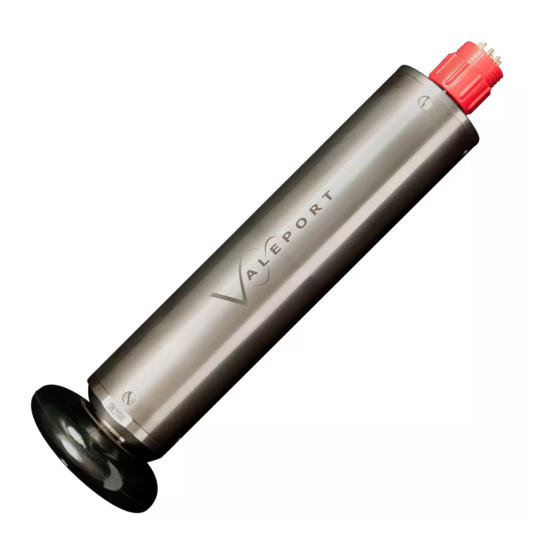
Model 803 ECM
Operating Manual
+44 1803 869292
sales@valeport.co.uk | support@valport.co.uk
www.valeport.co.uk
Advertisement
Table of Contents

Related Manuals for Valeport 803


Summary of Contents for Valeport 803
- Page 1 Date: March 2019 This document was prepared by the staff of Valeport Limited, the Company, and is the property of the Company, which also owns the copyright therein. All rights conferred by the law of the copyright and by virtue of international copyright conventions are reserved to the Company. This document must not be...
-
Page 2: Table Of Contents
............................. 15 6. Maintenance ............................. 16 6.1. Cleaning ............................ 16 6.2. Seal Sizes ............................ 16 7. Appendix 1 - Electrical Connections ............................. 17 7.1. RS232 Communications Lead ............................ 17 7.2. RS485 Communications Lead ............................ 17 Valeport Ltd © 2019 Page 2... - Page 3 7.4. RS232 Communications Lead with 4-20mA Analogue Output Pigtail ............................ 18 8. Appendix 2 - Filter Characteristics ............................. 19 8.1. 801/802/803 Digital Filter Characteristics - Attenuation dB ............................ 19 8.2. 801/802/803 Digital Filter Characteristics - Signal Ratio ............................ 19 9. Appendix 3 - Configuration Codes .............................
-
Page 4: Introduction
Available as a complete self-contained instrument, or with a separate sensor and electronics package, or even as an OEM system, the Model 803 will appeal both to operators who wish to improve their existing vehicles, and to manufacturers who want to offer it as an additional item in the sensor package. -
Page 5: Specification
(1 Hz default). Alternative formats are 0 – 10v (zero speed at 5v), or 0 – 5v (zero speed at 2.5v) for each channel. Calibration Held in EEPROM in unit. Page 5 Valeport Ltd © 2019... -
Page 6: Physical
0803805i - Model 803 ECM 1.2.4. Physical 1.2.4.1. Electronics Housing Integral Mount Material: Black Acetal or Titanium Size: 92mm Ø x 237mm length (Acetal) 76mm Ø x 237mm length (Titanium) Depth Rating: 1000m (Acetal), 3000m (Titanium) Weight: 0.5 kg in water (Acetal), 3.5kg (Titanium) - Page 7 Introduction 1.2.4.3. Dimensions Page 7 Valeport Ltd © 2019...
-
Page 8: Installation And Operation
0803805i - Model 803 ECM 2. Installation and Operation 2.1. Hardware 2.1.1. Physical Installation The EM sensor should be mounted in free flow and the X and Y axes are normal to the stem. The sensor has a flat surface on the Titanium sensor end cap, indicating that flow from that direction is Y +ve. -
Page 9: Electrical Connections
For test, setup and evaluation purposes, the unit should be connected to a PC using the interface lead (Y Lead) supplied. The Model 803 can output digital data in either RS232 or RS485 formats. Units are supplied as standard with RS232 interface leads, but if the user intends to operate the instrument in RS485 mode, then an RS485 interface lead should be purchased in place of or as well as an RS232 lead. -
Page 10: Changing The Baud Rate
0803805i - Model 803 ECM 2.2.2. Changing the Baud Rate There are four possible baud rates that may be set. They are 2400, 4800, 9600 and 19200. To enter the baud rate having already interrupted the unit with the ”#” code, send the command: #210 followed by “space”... -
Page 11: Reading Serial Number And Software Version
The RS 485 interface lead contains a KK systems RS485/RS232 adaptor. This adaptor can be used to input and output data at different baud rates, so if the user had changed the baud rate of the Model 803 itself, it will also be necessary to change the baud rates of the adaptor. -
Page 12: Optional Analogue Output
0803805i - Model 803 ECM 2.2.7. Optional Analogue Output The Model 803 has an optional analogue output made available by the addition of an extra circuit board inside the instrument (board number 0801507A). If fitted, this board gives a standard analogue output of +/- 5V full scale with +/- 11bit resolution, for each of the two channels (X and Y axes). -
Page 13: Filters
The data filter is a digital FIR filter and the unit automatically sets the filter to suit the selected data output rate. So that the 803 can be used for turbulent flow applications where users wish to recreate the flow characteristics, the filters are set so that the cut-off frequency is half the data rate. -
Page 14: Selecting The Output Protocol
Titanium counter sunk slotted screws that hold the housing on the bulkhead and sensor end cap. Undo the 3 screws at the connector end of the 803 and ease the end plate from the housing. There is an internal flexible cable at this end of the module. This requires disconnecting at the pye connector before proceeding to the electronics. -
Page 15: Trouble Shooting
3. Low battery power, low external voltage, current limit on external supply. If in any doubt about the performance of the unit, please contact the factory at the address shown on the front page of this manual. Page 15 Valeport Ltd © 2019... -
Page 16: Maintenance
0803805i - Model 803 ECM 6. Maintenance 6.1. Cleaning The EM sensor calibration will be affected by large amounts of marine growth as the water flow characteristics will be altered, so it advisable to periodically clean the sensor. The sensing electrodes should not be covered in grease or any form of insulating substance. -
Page 17: Appendix 1 - Electrical Connections
RS485 system, it may be necessary to swap the RS485 A and B connections to communicate successfully. Page 17 Valeport Ltd © 2019... -
Page 18: Rs232 Communications Lead With 4-20Ma Analogue Output
0803805i - Model 803 ECM 7.3. RS232 Communications Lead with 4-20mA Analogue Output Analogue Signal RS232 Power In MCIL10F SubConn Cable (Sockets in cable 9 way D (Banana Plugs) box) type Function 0v Supply Black plug + ve supply Red plug... -
Page 19: Appendix 2 - Filter Characteristics
Appendix 2 - Filter Characteristics 8. Appendix 2 - Filter Characteristics 8.1. 801/802/803 Digital Filter Characteristics - Attenuation dB 8.2. 801/802/803 Digital Filter Characteristics - Signal Ratio Page 19 Valeport Ltd © 2019... - Page 20 0803805i - Model 803 ECM Valeport Ltd © 2019 Page 20...
- Page 21 Appendix 2 - Filter Characteristics Page 21 Valeport Ltd © 2019...
-
Page 22: Appendix 3 - Configuration Codes
0803805i - Model 803 ECM 9. Appendix 3 - Configuration Codes Code Followed By Space and Operation #000 Password Sends the password for setting serial number etc #003 Nothing Returns the Serial number of the unit #004 New_serial_no<cr> Changes serial no. in serial eeprom to new_serial_no floating point number do not use decimal point serial numbers at the moment. - Page 23 #216 Y_DAC_Cal_Knots<cr> Sets Y DAC cal for Knots. #217 Nothing Returns DAC cal for Knots. #218 Speed Sets both DAC output voltages for desired speed (only used when in knots output mode). Factory set. Page 23 Valeport Ltd © 2019...
-
Page 24: Appendix 4 - Calibration
0803805i - Model 803 ECM 10. Appendix 4 - Calibration The calibration certificates for the X and Y channels are provided separately from this manual together with the instrument’s warranty certificate. The calibration certificates also include the serial numbers of the electronics unit and sensor. - Page 25 The second straight line starts from Max_lt1 and including it, up to Max_lt2 but not including it. The Third straight line starts from Max_lt2 and including it, up to Max_lt3 but not including it. Page 25 Valeport Ltd © 2019...
Need help?
Do you have a question about the 803 and is the answer not in the manual?
Questions and answers