Table of Contents
Advertisement
Quick Links
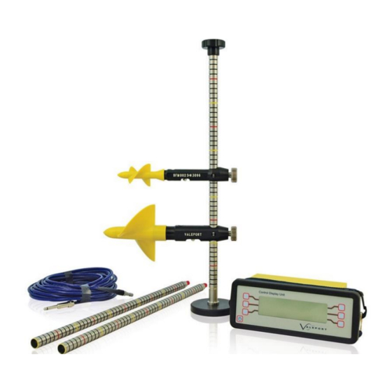
MODEL 001 & 002 FLOWMETER
OPERATING MANUAL
Document ID
MANUAL-1550859975-1 | issue: 1.1
Date:
August 2021
This confidential document was prepared by the staff of Valeport Limited, the Company, and is the
property of the Company, which also owns the copyright therein. All rights conferred by the law of
the copyright and by virtue of international copyright conventions are reserved to the Company.
This document must not be copied, reprinted or reproduced in any material form, either wholly or in
part, and the contents of this document, and any method or technique available there from, must
not be disclosed to any other person whatsoever without the prior written consent of the Company.
© 2021 Valeport Ltd
Valeport Ltd
St Peter's Quay
Totnes TQ9 5EW
United Kingdom
As part of our policy of continuous development, we reserve the right to alter, without prior notice, all
specifications, designs, prices and conditions of supply for all our equipment
Phone:
+44 1803 869292
email:
sales@valeport.co.uk
Web:
www.valeport.co.uk
Advertisement
Table of Contents

Related Manuals for Valeport BFM001


Summary of Contents for Valeport BFM001
- Page 1 Date: August 2021 This confidential document was prepared by the staff of Valeport Limited, the Company, and is the property of the Company, which also owns the copyright therein. All rights conferred by the law of the copyright and by virtue of international copyright conventions are reserved to the Company.
-
Page 2: Table Of Contents
Gauging Accessories ...................... 19 Figures ........................20 Figure 1 - Sectional Diagram BFM001 ................20 Figure 2 - BFM001 Impeller Shaft Setting ..............21 Figure 3 - Sectional Dagram of BFM002 ................ 22 Figure 4 - BFM002 Impeller Shaft Setting ..............23 Figure 5 - Reed Switch Assembly ................... - Page 3 A-2 Group Calibration of the 1178 Series Impeller ............28 A-2.1 Summary ......................... 28 A-2.2 Method and Result of Group Calibration ................ 29 A-2.2.1 Extract from Full Report....................29 A-2.2.2 Acknowledgements ....................... 29 © 2021 – Valeport Ltd Page | c...
-
Page 4: Design & Configuration
They are designed to accurately measure water velocity in open channels with flows varying from 0.03 m/s to 10 m/s (BFM001), or 0.05m/s to 5m/s (BFM002). The calibration of the meters is based upon Group Calibrations carried out by HR Wallingford to standards established by the British Standards Institution. -
Page 5: Assembly Instructions
Non‑Valeport Control Units It is advised that if the revolution counter being used is not of Valeport origin, no more than 5 milliamps are passed through the reed switch, to avoid damage. Valeport cannot accept responsibility for damage incurred when using non‑Valeport Control Units... -
Page 6: Maintenance Instructions
MANUAL-1550859975-1 | issue: 1.1 Maintenance Instructions The BFM001 and 002 flowmeters have been designed to require minimum maintenance under normal operating conditions. The Control Unit and wading/suspension cables should require no maintenance other than routine inspection and cleaning. It is recommended that the flowmeter itself is thoroughly washed and cleaned in fresh water after each deployment. -
Page 7: To Replace An Impeller Shaft
The above condition applies when the unit is dry and in perfect condition. If the impeller stops spinning suddenly or fails to spin smoothly, the impeller shaft may be bent or the clearances may require adjustment (see Figures 2/Figure © 2021 – Valeport Ltd Page | 4... -
Page 8: Operation With 0012B Control Display Unit
The 0012B contains calibration details for the Valeport meters BFM001, 002, 004, 007 and 050, and allows calibration coefficients for 4 other meters to be programmed in. User specific names for other meter calibrations can also be entered for ease of user identification. - Page 9 In free running mode the data is outputted at the end of each fixed average period and when the user presses the STOP key. The data string includes meter type, rev/sec, speed, standard deviation, pulses, time. © 2021 – Valeport Ltd Page | 6...
-
Page 10: Operation
Menu) reveals one of the six possible displays shown below, depending on what mode the unit was in when last used. DISPLAY 1: FIXED AVERAGE, USER SET TIME DISPLAY: DISPLAY 2: FIXED AVERAGE, USER SET PULSE COUNT DISPLAY: © 2021 – Valeport Ltd Page | 7... - Page 11 When there is 10 hours of battery life remaining (with backlight), this message will be displayed at the bottom right hand corner of the screen (see DISPLAY 1 for an example). The message will remain until batteries are replaced © 2021 – Valeport Ltd Page | 8...
-
Page 12: Setting Up Running Mode
The type of meter currently selected is displayed here. Toggle between the available meters by pressing the key. Pre-programmed meters available are the BFM001, 002, 004 (19mm), 004 (28mm), 007 & 050. For details of how to program the calibration details of another meter, refer to Section: Options Menu. -
Page 13: Options Menu
Proceed to Section: User Calibration Coefficients EXIT Puts the unit into Run Mode, using the hardware configurations selected (see Section: Running the Model 0012B). © 2021 – Valeport Ltd Page | 10... -
Page 14: Logging Menu
Increases the currently selected number by 1. DECREASE Decreases the currently selected number by 1. NEXT Selects the next number in the time/date sequence. EXIT Returns user to LOGGING MENU. Refer to Section: Logging Menu © 2021 – Valeport Ltd Page | 11... -
Page 15: Viewing Stored Data
UPLOAD Begins to upload data to PC. Screens similar to those shown below will appear EXIT Returns to LOGGING MENU. Refer to Section: Logging Menu © 2021 – Valeport Ltd Page | 12... -
Page 16: User Calibration Coefficients
O F F S E T 3 E N D 3 S L O P E 4 O F F S E T 4 E N D 4 E X I T > > > © 2021 – Valeport Ltd Page | 13... -
Page 17: Setting Calibration Coefficients
The Model 0012B will not be able to display speed data if the pulse output from the impeller exceeds 50Hz. The operating ranges of all Valeport impellers fall well within this, but if inputting calibration data for a different meter, check that the expected pulse frequency is below 50Hz. If a larger frequency is anticipated, contact Valeport Limited. -
Page 18: General Control Codes #000 - #014
First, decide if your calibration is a polynomial equation or a series of straight line fits. For line fits, proceed to Section: Straight Line Fits. For polynomial fits, proceed to Section: Polynomial Fits. © 2021 – Valeport Ltd Page | 15... - Page 19 For line fits less than four line fits the unused parameters should be filled in with zeros. For example, the calibration for the BFM001 is a two straight line fit, with equations: V = 0.013 + 0.2512n (up to 0.32 revs/sec) V = 0.008 + 0.2667n (from 0.32 up to 11.28 revs/sec)
- Page 20 #003 2 0 0 0.001 0.003 0.6 7.03 0.6 4.1 To change the name of the meter, type the correct #CODE followed by the new name (upper and lower cases are recognised). For example, to change the name from OTHER3 to BFM001, enter: #013 BFM001 When all required data has been input, enter #000, and the 0012B will automatically return to the Options Menu.
-
Page 21: Flowmeter Spares
Section 6 | Flowmeter Spares Flowmeter Spares Valeport maintains full spares, service and repair facilities for all its instruments. In the event of spares or additional items being required, the main sub-assemblies and spare parts are detailed below. BFM0011 Current meter fitted with 127 mm dia. x 0.27m pitch impeller BFM0021 Current meter fitted with 50 mm dia. -
Page 22: Gauging Accessories
Gauging Winch Fitted with 35m cable and connections for the BFM001/2 SK178L Large Gauging Winch with 100m cable and connections For full details on these products and Valeport's complete range of hydrological and oceanographic equipment, please consult the factory. © 2021 – Valeport Ltd... -
Page 23: Figures
Section 7 | Figures Figures 7.1 Figure 1 - Sectional Diagram BFM001 Figure 1 – Sectional Diagram BFM001 © 2021 – Valeport Ltd Page | 20... - Page 24 Model 001 & 002 Flowmeter Operating Manual MANUAL-1550859975-1 | issue: 1.1 7.2 Figure 2 - BFM001 Impeller Shaft Setting Figure 2 – BFM001 impeller shaft setting © 2021 – Valeport Ltd Page | 21...
- Page 25 Section 7 | Figures 7.3 Figure 3 - Sectional Diagram of BFM002 Figure 3 – sectional diagram of BFM002 © 2021 – Valeport Ltd Page | 22...
- Page 26 Model 001 & 002 Flowmeter Operating Manual MANUAL-1550859975-1 | issue: 1.1 7.4 Figure 4 - BFM002 Impeller Shaft Setting Figure 4 – BFM002 impeller shaft setting © 2021 – Valeport Ltd Page | 23...
- Page 27 Section 7 | Figures 7.5 Figure 5 - Reed Switch Assembly Signal Cable Reed switch holder assembly Figure 5 – reed switch assembly © 2021 – Valeport Ltd Page | 24...
-
Page 28: Eu Declaration Of Conformity - Ce Marking
Any changes or modifications to the product or accessories supplied, that are not authorised by Valeport Ltd, could void the CE compliance of the product and negate your authority to operate it. This product has demonstrated CE compliance under conditions that include the use of shielded cables. -
Page 29: Appendices
Standards Institution, BS3680, Part 8A, 1973. Application It applies to the BFM001 Meter fitted with the 125 mm (5 inch) diameter impeller, but only those fitted with the 8011 series impeller, introduced from June 1981. A systematic error would result if the calibration were applied, incorrectly, to any other type of Valeport meter. -
Page 30: A-1.5 Reliability
MANUAL-1550859975-1 | issue: 1.1 Reliability Over most of the flow speed range, above about 0.15 m/s, any particular BFM001 meter with 8011 type Impeller is expected (at 95 per cent confidence level) to perform within ±1.5 per cent of the indication of the group calibration. -
Page 31: Group Calibration Of The 1178 Series Impeller
Appendices Group Calibration of the 1178 Series Impeller As fitted to the Valeport "Braystoke" BFM002 flowmeter Summary It is customary to calibrate current meters individually, which is expensive and time consuming. For a family of physically identical meters a less costly and generally satisfactory alternative is a group calibration. -
Page 32: A-2.2 Method And Result Of Group Calibration
The above summary, report extract and following calibration tables are reproduced from HRS Report No. DE57 (Calibration B2/2), June 1982 with the kind permission of Hydraulics Research Station, Wallingford, England. For a full detailed description of the group calibration, please refer to this report. © 2021 – Valeport Ltd Page | 29...
Need help?
Do you have a question about the BFM001 and is the answer not in the manual?
Questions and answers