Table of Contents
Advertisement
Quick Links
Document Ref:
0801852a
Date:
08 August 2016
This document was prepared by the staff of Valeport Limited, the Company, and is the property of
the Company, which also owns the copyright therein. All rights conferred by the law of the
copyright and by virtue of international copyright conventions are reserved to the Company. This
document must not be copied, reprinted or reproduced in any material form, either wholly or in
part, and the contents of this document, and any method or technique available therefrom, must
not be disclosed to any other person whatsoever without the prior written consent of the
Company.
Valeport Limited
St Peters Quay
Totnes
Devon, TQ9 5EW
United Kingdom
As part of our policy of continuous development, we reserve the right to alter, without prior
notice, all specifications, designs, prices and conditions of supply for all our equipment.
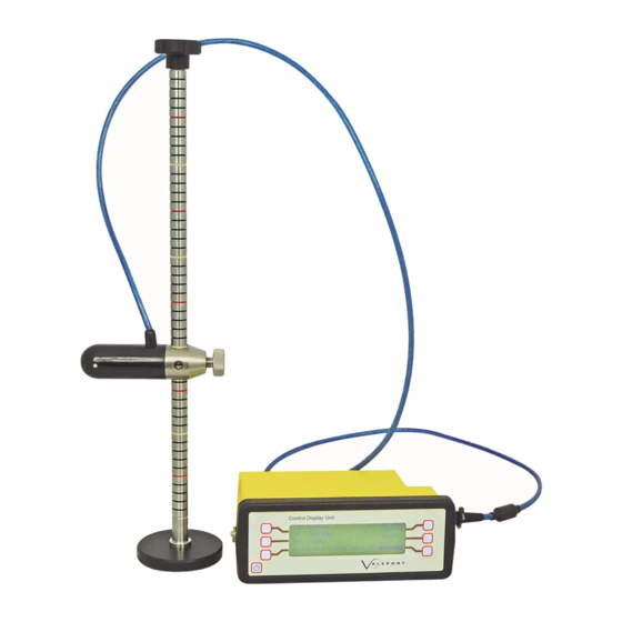
Model 801 EM
Current Meter
Operating Manual
Tel:
+44 1803 869292
e mail:
sales@valeport.co.uk
Web:
www.valeport.co.uk
Advertisement
Table of Contents

Related Manuals for Valeport 801 EM


Summary of Contents for Valeport 801 EM
- Page 1 Date: 08 August 2016 This document was prepared by the staff of Valeport Limited, the Company, and is the property of the Company, which also owns the copyright therein. All rights conferred by the law of the copyright and by virtue of international copyright conventions are reserved to the Company. This...
-
Page 2: Table Of Contents
Table of Contents Page 2 Page 2 Table of Contents 1. Introduction ............................. 3 2. Equipment ............................. 4 2.1. Standard 801 System ............................ 4 2.2. Wading Accessories ............................ 4 2.3. Options ............................ 4 3. Description ............................. 5 4. System Operation ............................. -
Page 3: Introduction
Introduction Page 3 1. Introduction This manual covers the operation of the Valeport Model 801 Electromagnetic Flow Meter. Flat Type - 0801001 Cylindrical Type - 0801002 © 2016 Valeport Ltd... -
Page 4: Equipment
Model 801 EM Current Meter Page 4 2. Equipment 2.1. Standard 801 System The standard 801 system has a choice of sensors and comprises the following. Both can be used with either 19 or 20mm diameter wading rods which customers may already have for use with... -
Page 5: Description
The sensor will detect negative flow and the same calibration is used, although there will normally be some interference caused by the turbulence from the wading rods. The unit is set to measure speeds up to 5 M/sec in both directions. © 2016 Valeport Ltd... - Page 6 Model 801 EM Current Meter Page 6 The system is calibrated as a combination of sensor with electronics in the Control Display Unit, and the serial number of both the probe and the CDU are displayed on the display on start up.
- Page 7 The optional analogue output is +/-5volts for the speed range +/-5 M/sec, and the analogue signal is based on the latest average figure shown on the CDU. The analogue output connector also enables external DC to be applied. © 2016 Valeport Ltd...
-
Page 8: System Operation
Model 801 EM Current Meter Page 8 4. System Operation 4.1. Setting Up To prepare the system for use: Clean the probe electrodes to remove any grease or dirt. Insert batteries [8 off 1.5v C type cells], if external power not being used. It is recommended that alkaline type cells are used for maximum life. -
Page 9: Running The Unit
If the unit is in logging mode, the current record number will be displayed at the top right hand side of the screen. If the data interface lead is connected, the end of average values will also be sent to the PC. © 2016 Valeport Ltd... -
Page 10: Setting Units, Averaging Mode And Averaging Period
Model 801 EM Current Meter Page 10 I N I T I A L I S I N G P L E A S E W A I T STOP Press to cease sampling. This will force an early end to an averaging period at the next second. -
Page 11: Option Menu
Section 5 for details of battery life with and without backlight. LOGGING MENU Allows access to LOGGING MENU. This enables the user to view or erase stored data, to extract it to a PC [via data interface lead], and © 2016 Valeport Ltd... -
Page 12: Logging Menu
Model 801 EM Current Meter Page 12 to set the unit date and time. Refer to Section 4.6. SUB OPTIONS This enables the user to go into the sub – options menu which allows direct EM communications with a PC [via data interface lead] for viewing EM data and setting of the calibration coefficients. - Page 13 Allows user to view the record currently selected. A display of the format shown below will be seen. Press EXIT on this screen to return to the VIEW DATA screen, allowing another record to be seen. EXIT Returns to the LOGGING MENU. Refer to Section 4.6. © 2016 Valeport Ltd...
- Page 14 Model 801 EM Current Meter Page 14 # I D E N T F F F R S P E E D + X . X X X S D = X . X X X P E R I O D...
-
Page 15: Sub Options Menu
C O M M S > > > < < < H I A L A R M + 1 . 2 A L A R M + 0 . 3 E X I T > > > © 2016 Valeport Ltd... -
Page 16: Analogue Output [Factory Fit Option]
Model 801 EM Current Meter Page 16 4.8. Analogue Output [Factory Fit Option] The analogue output is factory set to provide +/- 5v for the range +/- 5 m/s. The voltage is derived from a D/A from the last updated average velocity figure. Alternatives analogue outputs are available including 4-20mA where the Control Display Unit provides the power for the 4-20mA. -
Page 17: Power Supply
If the unit is left in standby, and if no button has been pressed for 5 minutes, the beeper emits 5 beeps to remind the user that the unit is still switched on. This feature does not operate when the CDU is connected to a PC for communications such as downloading data. © 2016 Valeport Ltd... -
Page 18: External Power [Factory Fit Option]
Model 801 EM Current Meter Page 18 5.3. External Power [Factory Fit Option] The unit will operate on an input voltage range of 7 to 15 vDC. The optional External DC power cable has 4mm plugs [Red +ve, Black -ve]. If these are connected using the wrong polarity, an internal fuse will blow. -
Page 19: Calibration
The calibration coefficients are stored within the micro-controller in an ASCII text string. The format of this string depends on the type of calibration (line fit or polynomial fit). The first part of the string will be the calibration function number, selected from the table © 2016 Valeport Ltd... - Page 20 The third straight line starts from Max_lt2 and including it , up to Max_lt3 but not including it. The last line limit [e.g. Max_lt3 in the example above] must be set to more than the maximum number of counts, and Valeport usually use the figure 40000. © 2016 Valeport Ltd...
-
Page 21: Adjusting Zero Offset
Zero reading in still water, - 0.005 m/sec - 5 mm/sec New zero offset in counts, - 6.45 – (-5) - 6.45 + 5 - 1.45 counts Note that it is important to use the correct signs © 2016 Valeport Ltd... - Page 22 Model 801 EM Current Meter Page 22 6.1.1.2. Method 2 – Reading Raw Real Time Counts Interrupt the unit using the #<cr> command detailed above Put the EM unit into NOCAL mode [i.e. to output data in raw counts], by entering #007 “space”...
-
Page 23: Care And Maintenance
Control Display Unit. In principle the calibration is for life, but as with most instruments it is advisable that check calibrations should be carried out on an annual basis. © 2016 Valeport Ltd...
Need help?
Do you have a question about the 801 EM and is the answer not in the manual?
Questions and answers