
Subscribe to Our Youtube Channel
Related Manuals for ADLINK Technology 6216-GL Series


Summary of Contents for ADLINK Technology 6216-GL Series
- Page 1 6208/6216-GL Series Multi-channel Analog Output Cards User’s Manual Manual Revision: 4.03 Revision Date: July 8, 2009 Part Number: 50-11234-2020 Advance Technologies; Automate the World.
- Page 2 6208/6216-GL Series User’s Manual Revision History Revision Release Date Description of Change(s) Document created 1.00 (Legacy documentation revised/converted to new system) Document created (legacy documentation revised/converted to new system) 3.22 2003/05/07 Specification Revision Initial Release Major revision of document flow and placement of content.
- Page 3 6208/6216-GL Series User’s Manual Preface Copyright 2009 ADLINK TECHNOLOGY INC. This document contains proprietary information protected by copy- right. All rights are reserved. No part of this manual may be repro- duced by any mechanical, electronic, or other means in any form without prior written permission of the manufacturer.
- Page 4 Chapter 1, Introduction: gives an overview of 6208/6216-GL Series features, applications, specifications and supporting software environments for use with the product. The layout of the 6208/6216-GL Series as well as its connectors and termination boards are presented. Chapter 2, Getting Started: describes how to install and configure the 6208/6216-GL Series.
- Page 5 6208/6216-GL Series User’s Manual Important Safety Instructions: Presents safety instructions all users must follow for the proper setup, installation and usage of equipment and/or software. Warranty Information: Presents important warranty information for users/manufacturers rights and responsibilities regarding ADLINK products and services.
- Page 6 6208/6216-GL Series User’s Manual Acronyms & Terminology The following terms are used throughout this document. This list is prepared in alphabetical order for clarity. µsec./µs - microsecond A/mA - (Ampere/amp/milliampere) a unit of electric current, or amount of electric charge per second...
- Page 7 6208/6216-GL Series User’s Manual IRQ/SERIRQ - Interrupt Request / Serial Interrupt Request LabVIEW™ - Laboratory Virtual Instrumentation Engineering Workbench, a visual programming language for platforms and development environments LCR - Local Configuration Registers LSB - Least Significant Byte MATLAB® - Matrix Laboratory, a numerical computing environ-...
- Page 8 The following list of documents may be used as reference materi- als to support installation, configuration and/or the operation of ADLINK PCI-6208/6216-GL Series Multi-channel Analog Output Cards. This list is prepared in alphabetical order (by vendor name, then by document title) for clarity.
- Page 9 Address: 9F, No.166 Jian Yi Road, Chungho City, Taipei County 235, Taiwan Tel: +886-2-8226-5877 Fax: +886-2-8226-5717 Email: service@adlinktech.com Ampro ADLINK Technology Inc. Address: 5215 Hellyer Avenue, #110, San Jose, CA 95138, USA Tel: +1-408-360-0200 Toll Free: +1-800-966-5200 (USA only) Fax: +1-408-360-0222 Email: info@adlinktech.com...
- Page 10 Address: 84 Genting Lane #07-02A, Cityneon Design Centre, Singapore 349584 Tel: +65-6844-2261 Fax: +65-6844-2263 Email: singapore@adlinktech.com ADLINK Technology Singapore Pte Ltd. (Indian Liaison Office) Address: No. 1357, "Anupama", Sri Aurobindo Marg, 9th Cross, JP Nagar Phase I, Bangalore - 560078, India Tel: +91-80-65605817 Fax: +91-80-22443548 Email:...
-
Page 11: Table Of Contents
1 Introduction ................ 1 Overview................1 Features................2 Applications ................. 2 Specifications............... 3 PCI-6208/6216-GL Series Card Layout....... 5 6208/6216-GL Series Pin Assignments....... 7 Termination Boards and Cables .......... 8 2 Getting Started ..............9 Installation Environment ............9 Package Contents ............. 10 Installation................ - Page 12 6208/6216-GL Series User’s Manual MATLAB® Data Acquisition Toolbox Adapter ....20 LabVIEW™ Data Acquisition VI Set ......21 VEE™ Interface for ADLINK DAQ Cards ..... 22 ActiveX Controls for ADLINK DAQ Cards ..... 23 4 Hardware Registers ............25 PCI PnP Registers ............. 25 Analog Output Control Register .........
-
Page 13: List Of Figures
6208/6216-GL Series User’s Manual List of Figures Figure 1-1: PCI-6208V-GL/6216V-GL Rev. C2 Layout ...... 5 Figure 1-2: PCIe-6208V/6216V-GL Layout ........5 Figure 1-3: cPCI-6208V-GL and cPCI-6216V-GL Layou ....6 Figure 1-4: cPCI-6208V/R-GL and cPCI-6216V/R-GL Layout ... 6 Figure 1-5: 6208V-GL CN1 Connector Pin Assignments....7 Figure 1-6: 6216V-GL CN1 Connector Pin Assignments.... - Page 14 6208/6216-GL Series User’s Manual This page intentionally left blank. List of Figures...
-
Page 15: List Of Tables
6208/6216-GL Series User’s Manual List of Tables Table 4-1: 6208/6216-GL Series I/O Address Map......26 Table 4-2: Analog Output Status Register ........27 Table 4-3: Digital Output Register........... 27 Table 4-4: Digital Input Register ............. 28 Table 4-5: Voltage DA Conversion Table ........29... - Page 16 6208/6216-GL Series User’s Manual This page intentionally left blank. List of Tables...
-
Page 17: Introduction
User’s Manual Introduction 1.1 Overview ADLINK 6208/6216-GL Series are 8-ch or 16-ch, 16-bit analog output cards. They each offer ±10 V output ranges and 25 V/µs slew rates. Each channel is equipped with a dedicated digital to analog converter, and the output value of each channel can be updated individually. -
Page 18: Features
6208/6216-GL Series User’s Manual 1.2 Features PCI-6208V-GL and PCI-6216V-GL are fully compatible with PCI-6208V and PCI-6216V, respectively. cPCI-6208V-GL, cPCI-6216V-GL, cPCI-6208V/R-GL and cPCI-6216V/R-GL are fully compatible with cPCI-6208V, cPCI-6216V, cPCI-6208VR and cPCI-6216VR, respectively. Supports a 32-bit 3.3 V or 5 V PCI bus, Plug and Play (PCI- 6208V/6216V-GL) ... -
Page 19: Specifications
6208/6216-GL Series User’s Manual 1.4 Specifications Voltage Output: Channels: 8 channels for the 6208V-GL 16 channels for the 6216V-GL Resolution: 16-bit (15-bit guaranteed) Voltage output range: ±10 V Voltage output driving capability: ±5 mA max. - Page 20 6208/6216-GL Series User’s Manual General Specifications: Operating temperature: 0°C to +50°C Storage temperature: -20°C to +80°C Humidity: 5% to 95% non-condensing Connector: 37-pin D-sub connector (female) Bus interface: 32-bit slave PCI bus Power Consumption: ...
-
Page 21: Pci-6208/6216-Gl Series Card Layout
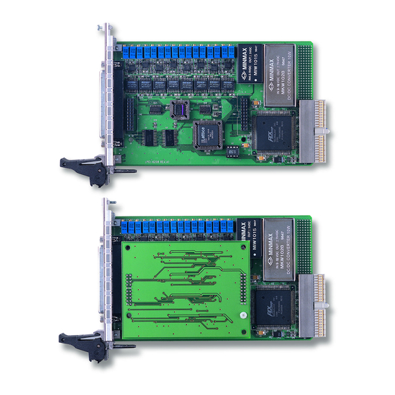
6208/6216-GL Series User’s Manual 1.5 PCI-6208/6216-GL Series Card Layout Figure 1-1: PCI-6208V-GL/6216V-GL Rev. C2 Layout 167,65 #4-40 23,80 42,15 57,15 19,00 59,05 Figure 1-2: PCIe-6208V/6216V-GL Layout Introduction... -
Page 22: Figure 1-3: Cpci-6208V-Gl And Cpci-6216V-Gl Layou
6208/6216-GL Series User’s Manual 160,00 19,90 (210,03) Figure 1-3: cPCI-6208V-GL and cPCI-6216V-GL Layou 160,00 20,00 (210,03) Figure 1-4: cPCI-6208V/R-GL and cPCI-6216V/R-GL Layout Introduction... -
Page 23: 6208/6216-Gl Series Pin Assignments
6208/6216-GL Series User’s Manual 1.6 6208/6216-GL Series Pin Assignments Figure 1-5: 6208V-GL CN1 Connector Pin Assignments Figure 1-6: 6216V-GL CN1 Connector Pin Assignments Introduction... -
Page 24: Termination Boards And Cables
The digital input and output pin names are specified as DIn and DOn respectively, where n = 0 to 3. 1.7 Termination Boards and Cables 6208/6216-GL Series cards are equipped with a 37-pin D-sub connector and compatible with the following termination boards.. -
Page 25: Getting Started
Only install equipment in well lit areas on flat, sturdy surfaces with access to basic tools such as flat and cross head screwdrivers. ADLINK 6208/6216-GL Series cards are electro-static sensitive components that can be easily damaged by static electricity. The card must be handled on a grounded anti-static mat. -
Page 26: Package Contents
6208/6216-GL Series User’s Manual 2.2 Package Contents Before continuing, check the package contents for any dam- age. If the contents are damaged, inform your dealer immedi- ately. Retain the shipping carton and packing materials for inspection. Obtain authorization from your dealer before return- ing any product to ADLINK. -
Page 27: Installation
Install the system manager, DAQManager, included on the All-in-one CD and accessible using the graphical user inter- face. Locate your 6208/6216-GL Series card and continue device installation. Also see Chapter 3 for Supporting Software details. NOTE: NOTE: Getting Started... -
Page 28: Installing Hardware
6208/6216-GL Series User’s Manual Installing Hardware PCI Configuration The PCI cards (or CompactPCI cards) are equipped with Plug and Play PCI controller, it can request base addresses and interrupt according to PCI standard. The system BIOS will install the sys- tem resources based on the PCI cards’... - Page 29 6208/6216-GL Series User’s Manual CompactPCI Installation Procedures 1. Read through this manual, and set the jumpers accord- ing to your application. 2. Turn off your computer and turn off all accessories con- nected to computer. 3. Remove the slot cover from the CompactPCI.
-
Page 30: Pci Device Configuration
6208/6216-GL Series User’s Manual 2.4 PCI Device Configuration Overview As plug and play component, a PCI card automatically requests an interrupt number through its PCI controller. The system BIOS responds with an interrupt assignment based on the card information and any known system parameters. These system parameters are determined by the installed drivers and the hardware load detected by the system. -
Page 31: Supporting Software
User’s Manual Supporting Software 3.1 Supporting Software ADLINK Technology Inc., a leading provider of high-performance, high-quality data acquisition cards and platforms, delivers robust software support for its comprehensive line of DAQ cards with varying form factors including PCI Express, PCI, CompactPCI, and PXI. -
Page 32: Windows Os Support & Drivers
6208/6216-GL Series User’s Manual 3.1.1 Windows OS Support & Drivers DAQPilot DAQPilot is a driver and SDK with a graphics-driven inter- face for various ADEs. DAQPilot comes as ADLINK's commit- ment to provide full support to its compre- hensive line of data acquisition products. -
Page 33: Daqmaster
6208/6216-GL Series User’s Manual DAQMaster The ADLINK DAQMaster is a smart device manager that opens up access to ADLINK data acquisition and test and measurement products. DAQMaster delivers an all-in-one interface which allows users to access a full support matrix to configure ADLINK Test and Measurement products. -
Page 34: Pcis-Dask (Legacy Drivers & Support)
6208/6216-GL Series User’s Manual 3.1.2 PCIS-DASK (Legacy Drivers & Support) ADLINK's DASK are advanced 32-bit kernel drivers for custom- ized DAQ application development. DASK enables users to per- form detailed operations and achieve superior performance and reliability from their data acquisition system. DASK kernel drivers now support the revolutionary Windows Vista OS. -
Page 35: Linux Os Support & Drivers
6208/6216-GL Series User’s Manual PCIS-DASK readies legacy users for Windows Vista and Other Windows 64-bit Editions: Supports Windows Vista 32 or 64-bit Editions Supports AMD64 and Intel x86-64 architectures Digitally-signed for Windows Vista 64-bit Edition Utilizes WOW64 subsystem to ensure that 32-bit applica-... -
Page 36: Third-Party Software Support
6208/6216-GL Series User’s Manual 3.1.4 Third-party Software Support MATLAB® Data Acquisition Toolbox Adapter The ADLINK DAQ-MTLB for MATLAB® inte- ® grates ADLINK components with the MAT- LAB® Data Acquisition Toolbox and enables users to control a wide range of ADLINK DAQ cards directly within the advanced MATLAB®... -
Page 37: Labview™ Data Acquisition Vi Set
6208/6216-GL Series User’s Manual LabVIEW™ Data Acquisition VI Set The DAQ-LVIEW PnP is a set of LabVIEW™ Virtual Instruments (VIs) that is fully-compatible with National Instrument's DAQ VIs. Based on the virtual instruments concept, DAQ-LVIEW PnP pro- vides four additional tool panels in LabVIEW™, including analog input, analog output, digital I/O, and timer/counter. -
Page 38: Vee™ Interface For Adlink Daq Cards
6208/6216-GL Series User’s Manual VEE™ Interface for ADLINK DAQ Cards Agilent VEE™ is a popular visual programming environment for data acquisition that includes data analysis and control. VEE™ provides a visual programming interface that allows users to cre- ate programs by connecting objects such as acquisition routines, buttons and displays in a flow diagram. -
Page 39: Activex Controls For Adlink Daq Cards
6208/6216-GL Series User’s Manual ActiveX Controls for ADLINK DAQ Cards ADLINK provides comprehensive ActiveX controls for DAQ devices. These ActiveX controls are designed to hide all hardware manipulation details so data acquisition operations can be achieved with only a few lines of codes. Furthermore, hardware configurations may be set with easy-to-use property pages while acquired data is returned in an event-driven manner. - Page 40 6208/6216-GL Series User’s Manual This page intentionally left blank. Supporting Software...
-
Page 41: Hardware Registers
6208/6216-GL Series User’s Manual Hardware Registers This chapter presents a detailed description of the 6208/6216-GL registers. This information is quite useful for the programmers who wish to handle the card using low-level programming. However, we suggest users have extended knowledge and experience using the PCI interface when performing machine level program- ming. -
Page 42: Analog Output Control Register
6208/6216-GL Series User’s Manual 4.2 Analog Output Control Register The 6208/6216-GL Series registers are all 16-bit. Users can access these registers with 16-bit I/O instructions. The follow- ing table shows the address of every analog output port relative to the base address. Note that the base address is assigned by the PCI BIOS. -
Page 43: Analog Output Status Register
6208/6216-GL Series User’s Manual 4.3 Analog Output Status Register The 6208/6216-GL Series cards use series bus architecture to communicate with digital-to-analog converters, hence there is a delay for digital values to be output. The data transfer rate for every DA data write is 2.2 µs, therefore the software driver must wait 2.2 µs before sending any other data to any analog... -
Page 44: Digital Input Register
6208/6216-GL Series User’s Manual 4.5 Digital Input Register Signals D4 through D7 are digital input signals from the CN1 connector. D4 - D7: digital input signal status. D0 - D3: read back signal from digital output channel. Offset Address 0x40... -
Page 45: Voltage Output Da Conversion
6208/6216-GL Series User’s Manual 4.6 Voltage Output DA Conversion The DA converter used in PCI-6208/6216-GL Series cards are 16-bit resolution with ±10 V bi-polar output ranges. Therefore, the data registers are all 16-bit sign values. The digital value ranges from -32768 (0X8000) to +32767 (0x7FFF) correspond to -10 V to +10 V respectively. - Page 46 6208/6216-GL Series User’s Manual This page intentionally left blank. Hardware Registers...
-
Page 47: Utilities & Calibration
6208/6216-GL Series User’s Manual Utilities & Calibration The ADLINK All-in-One CD provides a utility program located at: \\Driver Installation\NuDAQ PCI_cPCI\6208\Dos_bc\UTIL\6208util.exe \\Driver Installation\NuDAQ PCI_cPCI\6208\dos_msc\UTIL\6208util.exe for function testing of the 6208/6216-GL cards. The utility is a menu-driven graphical interface and operates under MS-DOS. -
Page 48: Running The Utility
6208/6216-GL Series User’s Manual 5.1 Running the Utility After installing/initializing DOS, you may execute the utility by typ- ing the following command (assuming your utility is located in the directory) at the DOS prompt. \ADLINK\DOS\6208\Util C> cd \ADLINK\DOS\6208\Util C> 6208UTIL The following diagram will be displayed on your screen. -
Page 49: Function Testing
6208/6216-GL Series User’s Manual 5.1.1 Function Testing From the main menu, when you choose < > Function Testing the function test menu will display. Select the device you have installed and would like to test by moving the cursor and press- ing <... -
Page 50: Calibration
During the calibration process, the calibration program will trig- ger the DMM to measure the actual output of every digital code (-32768 to +32767) generated by a 6208/6216-GL Series card. Then it creates a mapping table and records these data on a Flash memory chip. -
Page 51: Important Safety Instructions
6208/6216-GL Series User’s Manual Important Safety Instructions For user safety, please read and follow all instructions, WARNINGS, CAUTIONS, and NOTES marked in this manual and on the associated equipment before handling/operating the equipment. Read these safety instructions carefully. ... - Page 52 6208/6216-GL Series User’s Manual Never attempt to fix the equipment. Equipment should only be serviced by qualified personnel. A Lithium-type battery may be provided for uninterrupted, backup or emergency power. RISK OF EXPLOSION IF BATTERY IS REPLACED BY AN INCORECT TYPE.
Need help?
Do you have a question about the 6216-GL Series and is the answer not in the manual?
Questions and answers