
Related Manuals for powersoft D-Cell 504


Summary of Contents for powersoft D-Cell 504
- Page 1 D-Cell 504 service manual REV 1.2 June 2013 © 2012 - 2013 Powersoft Keep This Manual For Future Reference powersoft_DCell504_servman_en_v1.2...
- Page 2 Page intentionally left blank...
-
Page 3: Table Of Contents
The components to be replaced are clearly shown in red print D-Cell 504 to help their identification. At the end of this guide you can find a detailed list with the description and the respective Powersoft internal reference code of the spare parts. 2 Tools f Phillips PH 0 screwdriver. -
Page 4: Disassembly The Power Supply
FIGURE 2: AC Power supply: remove six screws. 4 Disassembly the amplifier board 1. Remove the six top cover fixing screws 2. Carefully remove the PSU board from the heat sink FIGURE 3: D-Cell 504 amplifier board: remove six screws. -
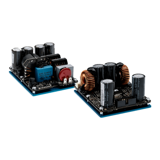
Page 5: Assembly Outline D-Cell 504 Power Supplies
5 Assembly outline D-Cell 504 power supplies FIGURE 5: D-Cell 504 DC power supply. FIGURE 4: D-Cell 504 AC power supply. -
Page 6: Assembly Outline D-Cell 504 Amplifier Board
6 Assembly outline D-Cell 504 amplifier board FIGURE 6: D-Cell 504 amplifier board - Top view. FIGURE 7: D-Cell 504 amplifier board - Bottom view. -
Page 7: Checking The Power Supply
7 Checking the power supply Evidence of a fault in the power supply stage is a blown main fuse (located close to the main switch). Before replacing it, check if the protection varistor is also blown. If not, disassemble the power supply board from the chassis and check all components as illustrated in the following paragraphs. -
Page 8: Failure Of The Inductor
9 Failure of the inductor If the 47 µH inductor in position L835T should fail, please replace it with a new inductor of the same nominal value but with a maximum current tolerated of 1.3 A. This specific power supply fault is present in first series power supplies equipped with inductors with an inadequate maximum current tolerance. -
Page 9: Failure Of The Mosfets
11 Failure of the MOSFETs 1. The MOSFETs are located on the bottom side of the amplifier’s PCB. 2. Components to be replaced: f Channel 1 MOSFETs Q200, Q201 f Channel 2 MOSFETs Q500, Q501 We recommend to carefully position the Sil-Pads to ensure the proper heat exchange between the com- ponents and the chassis. -
Page 10: Spare Part List
13 Spare part list D-Cell 504 Powersoft Description Position code Fuse 3.15A 250VDc (5x20mm) Fast FU000020 Main switch CF Series VR000006 VARISTOR S20K300 RV800T PTVA 47UH 1.3A H=14mm LI000015 L835T D=9.4mm FUSE 10A 6.1mmx2.69mm FAST F FUS00001 F800T, F801T serie451 LITTELFUSE... - Page 11 Page intentionally left blank...
- Page 12 Via Enrico Conti, 5 50018 Scandicci (FI) Italy Tel: +39 055 735 0230 Fax: +39 055 735 6235 General inquiries: info@powersoft.it Sales: sales@powersoft.it Application & technical support: support@powersoft.it Service & maintenance: service@powersoft.it www.powersoft-audio.com © 2012 - 2013 Powersoft powersoft_DCell504_servman_en_v1.2...
Need help?
Do you have a question about the D-Cell 504 and is the answer not in the manual?
Questions and answers