powersoft T Series Service Manual
Hide thumbs
Also See for T Series:
- User manual (45 pages) ,
- Quick manual (42 pages) ,
- Application notes (9 pages)
Advertisement
Table of Contents
- 1 Service Precautions
- 2 Replacing the Filters
- 3 Front Panel Introduction
- 4 Rear Panel Introduction
- 5 Front Panel Board
- 6 Mainboard Layout
- 7 Front Board Layout
- 8 Disassembling Procedure
- 9 Troubleshooting
- 10 Checking the Fan
- 11 Menu System
- 12 Product Code
- 13 Preliminary Stages
- 14 Final Test
- 15 Replacement Parts
- 16 Safety Precautions
- Download this manual
Advertisement
Table of Contents

Related Manuals for powersoft T Series


Summary of Contents for powersoft T Series
- Page 1 T-Series Platform T302 T302 T602 T602 T902 T902 T304 T304 T604 T604 T904 T904 Service Manual ©2017 Powersoft Keep this manual powersoft_T-Series_servman_en_v5.2 for future reference...
- Page 2 Intentionally left blank...
- Page 3 T-SERIES | SERVICE MANUAL Quattrocanali Service Manual Structure Safety Information Index Equipment Requirement Service Precautions Notes on Soldering Notes on Replacing Parts Serial Number Labels Mac Address Labels Description of The Amplifer Parts External 5.1.1 Replacing the Filters 5.1.2 Front Panel Introduction 5.1.3 Rear Panel Introduction Internal...
- Page 4 T-SERIES | SERVICE MANUAL Resetting the IP Address via Front Panel Menu Checking of the Firmware using ArmonìaPlus 1.3 Updating of the Firmware using Dante Controller T-Series Hardware Composition Part Number “Golden Sample” for Authorize Service Center for Troubleshooting Flowcharts For Repair Rev2.0 Replacement Parts T-Series Spare Parts Rev.
- Page 5 T-SERIES | SERVICE MANUAL Troubleshooting Structure SYMPTOM AREA SYMPTOM POSSIBLE CAUSES CHECK ACTIONS AUDIO No Audio DSP Board HW Check Internal LEDs Swap Golden Sample DSP Board FW ArmonìaPlus Update Firmware Flat Cables Check any damaged Swap Golden Sample Main Board Check Internal LEDs Swap Main Board Visual Inspection / Check...
- Page 6 Internal LEDs Checks - DSP Board - Normal Operating Conditions identification. At the end of this guide you can find a detailed list with the description and the respective Powersoft internal Checking the Fan reference code of the spare parts.
-
Page 7: Service Precautions
4.2 Notes on REPLACING PARTS About the AMP Module The amplifier module of this unit is able to correspond to repairing in the component manufacturer (Powersoft Company). And it holds charge-free warranty period for 16 months after production. 4.3 Serial Number Labels The details of the Serial Label is as follows. -
Page 8: Replacing The Filters
T-SERIES | SERVICE MANUAL 5. Description of The Amplifer Parts 5.1 External 5.1.1 Replacing the Filters The left side and right side panels can be extracted by unscrewing the screw with a T9 Torx Screwdriver on both side of the Amplifier, releasing them which holds them in place. -
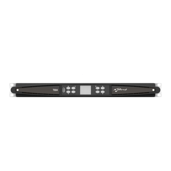
Page 9: Front Panel Introduction
T-SERIES | SERVICE MANUAL 5.1.2 Front Panel Introduction Control Panel USB Port Speaker Presets CH 1 - ON/STBY (2s hold) CH 2 - COGWHEEL (2s hold) Control Panel CH 3 (4 CH models) - Back CH 1 CH 4 (4 CH modles) - Apply CH 2 Toggle Between Screens CH 3 (4 CH models) -
Page 10: Rear Panel Introduction
T-SERIES | SERVICE MANUAL 5.1.3 Rear Panel Introduction T302 - T602 T304 - T604 Output Section Network Connectors T302 - T602 T304 - T604 DANTE / ETH 1 (RJ45) CH 1 (1+/-) | CH 2 (2+/-) CH 1 (1+/-) | CH 2 (2+/-) DANTE / ETH 2 (RJ45) CH 2 (1+/-) | n.c. -
Page 11: Front Panel Board
T-SERIES | SERVICE MANUAL 5.2 Internal 5.2.1 Main Module Locations Layout Rear Panel Board Colour Description DSP Board Fan + Fan’s Duct Main Board 2 CH REAR Rear Panel Front Panel EPROM: Amplifier’s Model Amplifier’s Serial Number Amplifer’s MAC Address 4 CH REAR Eprom Front Panel Board... -
Page 12: Mainboard Layout
T-SERIES | SERVICE MANUAL 5.2.2 Main Board Layout Layout Old Versions New Versions Colour Description CH4 Power Amp CH3 Power Amp CH2 Power Amp CH1 Power Amp Output Cable + Bulk Capacitors & Zobel Resistors Network PFC Converter Colour Description EMI Filter + Fuses Fuse A PSU Control Section... - Page 13 T-SERIES | SERVICE MANUAL 5.2.3 Main Board MOSFETs & Diodes Layout PFC 2 CH 4 Diodes MOSFETs PFC 2 CH 3 MOSFETs MOSFETs CH 2 PFC 1 MOSFETs MOSFETs CH 1 MOSFETs PFC 1 Diodes...
- Page 14 T-SERIES | SERVICE MANUAL 5.2.4 DSP Board Layout Layout Colour Description Audio Control Section DANTE Section 5.2.5 Rear Board Layout 4CH Rear 2CH Rear Layout Colour Description Output Port 1 & 2 AES3 input & Output Analog Input Port 1 to 4 Network Ethernet &...
-
Page 15: Front Board Layout
T-SERIES | SERVICE MANUAL | SERVICE MANUAL 5.2.6 Front Board Layout Layout Colour Description USB Port Buttons LCD Display Flat Cables Connectors... -
Page 16: Disassembling Procedure
T-SERIES | SERVICE MANUAL 6. Disassembling Procedure 6.1 Removing the Amplifier’s Cover By means of a T20 Torx Screwdriver, remove the 8 screws highlighted yellow on the Both Side of the Amplifier. By means of a T9 Torx Screwdriver, remove the screw highlighted in green on the Rear of the Amplifier. - Page 17 T-SERIES | SERVICE MANUAL 6.2 Fan Disassembling Unclip the fan’s duct by gently unclipping the retainer indicated in the portrayed picture. Lift and remove the fan’s duct. Unplug the fan’s connector. Note that the 2 screws highlighted in the following picture (yellow) sould not be present nor inserted.
- Page 18 T-SERIES | SERVICE MANUAL 6.3 Main Board Disassembling Unplug the mains’ Faston connectors. Unclip the safety retainer from the ground connector Proceed by removing the 3 flat cables connecting the Main Board to the DSP Board (highlighted in Orange)
- Page 19 T-SERIES | SERVICE MANUAL Focus your attention on the Output’s Fastons. Pull the Fastons Connectors Upwards. Refer to the following diagrams when reassembling the amplifier. Cable Number Cable Color Cable Number Cable Color Gray Yellow Brown White Black Blue Orange...
- Page 20 T-SERIES | SERVICE MANUAL Gently remove the Eprom (purple) and place in the new Main Board With a Thox 10 screwdriver, remove the 8 screws highlighted (yellow) in the picture below. It is now possible to extract the Main Board from the chassis, please do so by gently pivoting it towards the front of the amplifier by pulling upwards and outwards on the heatsink.
- Page 21 T-SERIES | SERVICE MANUAL 6.4 DSP Board Disassembling Gently remove all the flat cables connectors highlighted in orange & green as indicated. By means of a T10 Torx screwdriver, remove the 4 screws highlighted in red. Gently lift the DSP Board upwards the front of the amplifier, It is now possible to remove the DSP Board from the chassis.
-
Page 22: Troubleshooting
T-SERIES | SERVICE MANUAL 6.6 Rear Board Disassembling After removing the DSP-D Board, unplug the Outputs’ connector Fastons upwards. By means of a T9 Torx screwdriver, remove the 17 screwshighlighted in yellow. By means of a T10 Torx screwdriver, remove the 3 screws hightlighted in green. It is now possible to remove the Rear Board from the rear panel. - Page 23 T-SERIES | SERVICE MANUAL 7.2 Internal LEDs Checks - Power Supply Section - Normal Operating Conditions Main Board PSU Section Main Board Colour Status Action Colour Status Action +RAIL None None GREEN* GREEN -RAIL None None GREEN* GREEN None GREEN * The luminisity of these 2 LEDs is dimmed when the amplifier is in “Idle”...
- Page 24 T-SERIES | SERVICE MANUAL 7.3 Internal LEDs Checks - Main Board - AMP Section - Normal Operating Conditions NOTE: If any of the Channel “ENA” LED was Blinking “GREEN”, Colour Status Action Measure the Rail Fuses, Replace the Main Board if required. None If any of the Channel “FAULT”...
- Page 25 T-SERIES | SERVICE MANUAL CH3 / CH4 Fuses Colour Status Action Replace Fuse Replace Fuse CH1 / CH2 Fuses Colour Status Action Replace Fuse Replace Fuse...
- Page 26 T-SERIES | SERVICE MANUAL 7.4 Internal LEDs Checks - DSP Board - Normal Operating Conditions Make sure that the plug is correctly inserted in the ETH Port. Colour Status Action Colour Status Action None BLINKING None GREEN GREEN None BLINKING None ORANGE GREEN...
-
Page 27: Checking The Fan
T-SERIES | SERVICE MANUAL 7.5 Checking the Fan Remove the FAN’s connector as portrayed. With a multimeter, check the R361 Resistor. R361: 0.12 Ω Connect the fan to a DC power supply, and check its consumption as portrayed on the picture. +12 Vdc 1.3 A +12 Vdc 1.3 A 1.3 A (±... - Page 28 T-SERIES | SERVICE MANUAL 7.6 Checking the Mains Fuses & Auxilliary Fuses Remove the fuses from its housing and check it with a Multimeter.
- Page 29 T-SERIES | SERVICE MANUAL 8. T-Series Display Error Message ERROR TYPE DISPLAY MESSAGE DESCRIPTION WARNING “HIGH MAINS VOLTAGE” Mains close to upper limit, warning WARNING “LOW MAINS VOLTAGE” Mains close to lower limit, warning WARNING “HIGH TEMP” Temperature of power supply too high, warning WARNING “HIGH TEMP”...
- Page 30 T-SERIES | SERVICE MANUAL 9. Dante Controller & Updater 9.1 Brief Intro about Dante Dante is the de facto standard digital media networking solution, using standard IP infrastructure to network devices, and making interoperability easy and reliable. It distributes uncompressed, multi-channel digital media via standard Ethernet networks, with near- zero latency and perfect synchronization.
- Page 31 T-SERIES | SERVICE MANUAL 9.3. Updating Firmware - Initialize Dante Board Use the ‘Home’ tab to update your Dante devices. Click the arrow icons to expand and collapse the sections. Updates Available The Updates Available section of the Home tab lists devices that have been discovered on your Dante network which are eligible for a firmware update (devices for which there is new firmware available in the Dante Updater database).
- Page 32 T-SERIES | SERVICE MANUAL 9.4 About Failsafe 9.4.1 What is failsafe mode? All Dante hardware modules use software loaded from Flash memory as part of their operation. As with any storage device, it is possible to corrupt the data on the Flash part, potentially rendering it unusable, if there are interruptions while writing to the Flash device.
- Page 33 T-SERIES | SERVICE MANUAL 9.5 Using Failsafe Recovery Basic Steps To recover Dante devices in safe mode: 1. Ensure the computer running Dante Firmware Update Manager and the device you wish to recover are on the same IP subnet. (follow instruction n chapter 11.6 from point 1 to 13) 2.
- Page 34 T-SERIES | SERVICE MANUAL Screen 2- Finding devices for safe recovery This screen indicates that Firmware Update Manager has detected at least device in safe mode, and is scanning the network for the full list. It should take less than a minute to find all applicable devices. When you are sure that all your safe mode devices have been found, click Stop Scan.
- Page 35 T-SERIES | SERVICE MANUAL 9.6 Dante Dynamic IP Restore 1. Download the last version of Dante controller (or at least 4.06.xx version) and install it on your PC (the download is available on https://www.audinate.com/products/software/dante-controller) 2. Execute Dante Controller on your PC 3.
- Page 36 T-SERIES | SERVICE MANUAL 5. Take note about the IP address set on the device (ex. 169.254.200.121) 6. Close Dante controller 7. On your PC enter Control Panel. 8. Open “Network and sharing center” 9. Click on “Change adapter setting” 10.
- Page 37 T-SERIES | SERVICE MANUAL 12. Select TCP/IPv4 and click on properties. The following windows will be shown 13. Take note of your original configuration and then configure your computer’s network interface with a static IP address in the same range as the IP address for the Dante device. Use the same values for the first three octets and choose a different number from 1 to 255 for the last octet (in this example Dante IP address is 169.254.200.121 , then choose 169.254.200.1 for your PC IP address).
- Page 38 T-SERIES | SERVICE MANUAL 10. Testing the Unit via ArmonìaPlus 1.3 Connect the unit to a PC via the Ethernet slots GREEN led ON (flashing) Link/Activity indicator: Blinking – There is activity on this port. Off – No link is established GREEN led ON (solid) Connection is correctly established between the two devices YELLOW led ON ETH speed connection...
- Page 39 T-SERIES | SERVICE MANUAL The Unit and its Serial Number should appear within 5 seconds By hover the mouse cursor on top of the unit’s icon, it is possible to check the Model, Serial, Retel(IP Address), Firmware Apply a 1KHz 1Vpp audio signal to CH1 Check for presence of the signal in all the other channel’s VMeters Drag and drop the unit into the Workshop, notice the ‘white/red Function...
- Page 40 T-SERIES | SERVICE MANUAL 11. T-Series Platform DSP Rescue Procedure 1. In the event when you not able to Boot Up your Amplifer & having this Sceen Shot “Hanged” 2. Connect the PC to the amplifier via ETH port 192.168.5.1 like as 3.
- Page 41 T-SERIES | SERVICE MANUAL 192.168.5.200 8. Connect your PC to the amp writing in the address bar of your browser. The following screen will be shown: Select “upgrade firmware”. 9. The following screen will be shown: Click on “Browse” upgradet-v1.8.7.16.zip 10.
- Page 42 T-SERIES | SERVICE MANUAL 12. The procedure will take approx. 10 min. 13. When the procedure is finished you will see the Upgrading bar totally blue colored. 14. To end the Update the amplifier must reboot and back to normal condition as after power up 15.
-
Page 43: Menu System
T-SERIES | SERVICE MANUAL 12. Menu System : Press and Hold the CH2/Cogwheel Button for 2 Seconds. MAIN VIEW OUTPUT MUTE SPEAKER LEVEL Step Size SPEAKER DELAY Step Size MATRIX Custom Matrix SOURCE SELECT SNAPSHOT Preview Load to Single SPEAKER CONFIG Custom Outputs SPEAKER PRESET... - Page 44 T-SERIES | SERVICE MANUAL 13. Resetting the IP Address via Front Panel Menu Turn the Amplifier On. Press the Top Leftmost Button (YELLOW) to 9.1 NET CONFIG “AMP STATUS” Press the Button (GREEN) to Select the IP Address Mode (DYNAMIC IP or STATIC IP) To Reset the IP Address, Press the Button (GREEN) to “COMFIRM”...
- Page 45 Firmware: 1.8.7.16 (NEW VERSION) 15. Updating of the Firmware using Dante Controller Connect the unit to a PC via the Dante slots. Click on the Link to proceed to Powersoft Website. Launch Dante Controller Application. Click on the “Icon” to Update Dante Firmware.
- Page 46 T-SERIES | SERVICE MANUAL Click “Update Dante Firmware”. Check the “Box” & Click “Start” to begin. Click “Browse”. Click “OK” to acknowledge. Select Correct Firmware & Click “Open”. Updating of Firmware begins. Check the “Box” & Click “Next”. Completed Upgrading & Click “OK” to exit. Click “Yes”...
-
Page 47: Product Code
T-SERIES | SERVICE MANUAL 16. T-Series Series Hardware Composition Part Number Product Code Main Front Rear T602 PF00H471 SMD01149.R T302 PF00H472 SMD01096.R SM001148.R T902 PF00H477 SMD01239.R SM001140.T.R FR000003.R T604 PF00H475 SMD01094.R T304 PF00H474 SMD01095.R SM001147.R T904 PF00H476 SMD01238.R 17. “Golden Sample” for Authorize Service Center for Toubleshooting Part Number Model DSP Board... - Page 48 T-SERIES | SERVICE MANUAL 18. Flowcharts For Repair Rev2.0 PF00H471 - T602 PF00H472 - T302 PF00H474 - T304 PF00H475 - T604 PF00H476 - T904 PF00H477 - T902 List: • Preliminary Stage • Main Board Fault 1 • Main Board Fault 2 •...
-
Page 49: Preliminary Stages
T-SERIES | SERVICE MANUAL Preliminary Stages... - Page 50 T-SERIES | SERVICE MANUAL Main Board Fault 1...
- Page 51 T-SERIES | SERVICE MANUAL Main Board Fault 2...
- Page 52 T-SERIES | SERVICE MANUAL Display and Buttons Check...
- Page 53 T-SERIES | SERVICE MANUAL HV Test Fail...
- Page 54 T-SERIES | SERVICE MANUAL Fail Evaluation...
-
Page 55: Final Test
T-SERIES | SERVICE MANUAL Final Test 1... - Page 56 T-SERIES | SERVICE MANUAL Final Test 2...
- Page 57 Step-Up/Down/Inverting switch Online www.octopart.com ON-SEMICONDUCTOR MC33063AP1G U304 ICS00414 Si8234BB-D-IS1 4.0 AMP Online www.octopart.com SILICON LABORATORIES Si8234BB-DIS1 U1007-U2007-U3007-U4007 IS000082.XX ISL Hi-Flow 160X32 SER300P th2 Powersoft IS000085.XX ISL Hi-Flow 88X32 SER_300P Powersoft Q1000-Q1003-Q2000-Q2003- MO000039 FDH45N50F___________|TO247____ Online www.octopart.com INFINEON FDH45N50F-F133 Q3000-Q3003-Q4000-Q4003 MO000048 IXTH48N65X2_________|TO247 Online www.octopart.com...
- Page 58 T-SERIES | SERVICE MANUAL Layout of Main Board (Top)
-
Page 59: Replacement Parts
NOTE: THE SUFFIX XX IS REFERRED TO THE LATEST VERSION OF THIS ITEM MANUFACTURED ITEM PICTURE PART NUMBER DESCRIPTION FLAT CABLE 20P L 45mm Order to Powersoft CB000665.XX Reference Prime Manufactured Reference MPN code 4CH 34p INTERNAL CONNECTION Order to Powersoft CB000666.XX... - Page 60 T-SERIES | SERVICE MANUAL NOTE: THE SUFFIX XX IS REFERRED TO THE LATEST VERSION OF THIS ITEM MANUFACTURED ITEM PICTURE PART NUMBER DESCRIPTION T-SERIES FRONT LABEL Order to Powersoft ET000701.XX Reference Prime Manufactured Reference MPN code T-SERIES LOGO PWT FRONT RIGHT Order to Powersoft ET000740.XX...
- Page 61 T-SERIES | SERVICE MANUAL NOTE: THE SUFFIX XX IS REFERRED TO THE LATEST VERSION OF THIS ITEM MANUFACTURED ITEM PICTURE PART NUMBER DESCRIPTION 4CH - FILTER HEATSINK Order to Powersoft FI000032.XX Reference Prime Manufactured Reference MPN code T-SERIES FRONTAL FILTER Order to Powersoft FI000033.XX...
- Page 62 DESCRIPTION T-SERIES EXTRACTOR GASKET Order to Powersoft GU000105.XX Reference Prime Manufactured Reference MPN code T SERIES FRONT GASKET Order to Powersoft GU000126.XX Reference Prime Manufactured Reference MPN code 24LC512 Series 512 Kb I2C 2 Wire (64K X 8) 2.5 V Serial...
- Page 63 T-SERIES | SERVICE MANUAL NOTE: THE SUFFIX XX IS REFERRED TO THE LATEST VERSION OF THIS ITEM MANUFACTURED ITEM PICTURE PART NUMBER DESCRIPTION T-SERIES FRONTAL PLATE LH Order to Powersoft ME001328.XX Reference Prime Manufactured Reference MPN code T-SERIES FRONTAL CASTING Order to Powersoft ME001332.XX...
- Page 64 NOTE: THE SUFFIX XX IS REFERRED TO THE LATEST VERSION OF THIS ITEM MANUFACTURED ITEM PICTURE PART NUMBER DESCRIPTION 4CH/STD/MAIN + DISS FOR REPAIR (T604 MAIN BOARD) SMD01094.R Order to Powersoft Reference Prime Manufactured Reference MPN code 4CH/LGT/MAIN + DISS FOR REPAIR (T304 MAIN BOARD) SMD01095.R Order to...
- Page 65 NOTE: THE SUFFIX XX IS REFERRED TO THE LATEST VERSION OF THIS ITEM MANUFACTURED ITEM PICTURE PART NUMBER DESCRIPTION 4CH/HV/MAIN + HEATSINK FOR REPAIR (T904 MAIN BOARD) SMD01238.R Order to Powersoft Reference Prime Manufactured Reference MPN code 2CH/HV/MAIN + HEATSINK FOR REPAIR (T902 MAIN BOARD) SMD01239.R Order to...
- Page 66 (FRONT & REAR SCREW) Order to Online VI000426 Reference www.octopart.com Prime Manufactured BOSSARD Reference MPN code 3233663 BLOWER 120X120X32 _12V_1.12A FOR REPAIR Order to Powersoft VN000040 Reference Prime Manufactured Reference MPN code VARISTOR S20K385 Order to Online VR000007 Reference www.octopart.com Prime Manufactured EPCOS...
- Page 67 LITTELFUSE MTS1200A GU000096.XX AIR BOX GASKET - F.CABLE BLOCK Powersoft GU000105.XX T-SERIES EXTRACTOR GASKET Powersoft GU000126.XX T SERIES FRONT GASKET Powersoft IC000117 24LC512 Series 512 Kb I2C Powersoft IS000081.XX 4CH - MAKROFOL BASE ISOLATOR Powersoft KT000475.XX KIT CB T-FRONT 10P+12P MM +GU Powersoft KTXXXXXX.XX...
- Page 68 T-SERIES | SERVICE MANUAL 21. Location to Paste the Anti-Tamper Label after Repaired. For every In-Warranty repair, you have to paste the Anti-Tamper Label on the instructed position. Upon receiving the Faulty Unit, inspect the Label to see if there’s any Tampering.
-
Page 69: Safety Precautions
T-SERIES | SERVICE MANUAL IMPORTANT SAFETY ADDENDUM The aim of this addendum is to describe the safety precautions to be undertaken when servicing any Powersoft amplifier/module. WE RECOMMEND THAT ALL SERVICE OPERATIONS ARE CARRIED OUT BY A TRAINED TECHNICIAN IF NOT EXPLICITLY STATED OTHERWISE, DISCONNECT THE AMPLIFIER FROM THE MAINS. - Page 70 Intentionally left blank...
- Page 71 Powersoft S.p.A. Via Enrico Conti, 5 50018 Scandicci (FI) Italy Tel: +39 055 735 0230 Fax: +39 055 735 6235 www.powersoft.com Data are subject to change without notice. For latest update please refer to the online version available on www.powersoft.com...
Need help?
Do you have a question about the T Series and is the answer not in the manual?
Questions and answers