Sign In
Upload
Download
Table of Contents
Contents
Add to my manuals
Delete from my manuals
Share
URL of this page:
HTML Link:
Bookmark this page
Add
Manual will be automatically added to "My Manuals"
Print this page
×
Bookmark added
×
Added to my manuals
Manuals
Brands
AAON Manuals
Control Unit
MODGAS-X
Technical manual
AAON MODGAS-X Technical Manual
Hide thumbs
1
2
Table Of Contents
3
4
5
6
7
8
9
10
11
12
13
14
15
16
17
18
19
20
21
22
23
24
25
26
27
28
29
30
31
32
33
34
35
36
37
38
page
of
38
Go
/
38
Contents
Table of Contents
Troubleshooting
Bookmarks
Table of Contents
Table of Contents
Overview
General Information
Dimensions
Figure 1: MODGAS-X Module Dimensions
Wiring
Important Wiring Considerations
Table 1: Electrical and Environmental Requirements
Single Modulating Valve no Staging - Stand-Alone Wiring
Figure 2: Single Modulating Valve no Staging Stand-Alone Wiring Diagram
Single Modulating Valve no Staging - Communicating Wiring
Figure 3: Single Modulating Valve no Staging Communicating Wiring Diagram
Single Modulating Valve and up to 14 Stages of Fixed Heat Stand-Alone
Figure 4: Single Modulating Valve - Stand-Alone Wiring Diagram
Figure 5: Single Modulating Valve and 14 Stages of Fixed Heat - 12 Relay E-BUS Expansion Module
Two Modulating Valves and up to 13 Stages of Fixed Heat Stand-Alone
Figure 6: Two Modulating Valves - Stand-Alone
Figure 7: Two Modulating Valves and 13 Stages of Fixed Heat - 12 Relay E-BUS Expansion Module
Two Modulating Staged Valves - Stand-Alone Wiring
Figure 8: Two Modulating Staged Valves Stand-Alone Wiring Diagram
Two Modulating Staged Valves - Communicating Wiring
Figure 9: Two Modulating Staged Valves Communicating Wiring Diagram
Inputs and Outputs
Table 2: MODGAS-X Inputs and Outputs
Sequence of Operation
Operating Modes
Table 3: Heating Mode Voltage/Signal
Lcd Screens
Navigation Keys
Figure 10: LCD Display and Navigation Keys
Table 4: Navigation Key Functions
Table 5: Editing Key Functions
Main Screens Map
MODGAS-X Screens
Status and Alarms Screens
Setpoint and Force Screens
Protected and Diagnostic Screens
Configuration Screens
Troubleshooting
LED Diagnostics
Table 6: STATUS LED Blink Codes
Table 7: STATUS LED Blink Codes
Figure 11: MODGAS-X LED Locations and Descriptions
Alarms
SAT Sensor Testing
Table 8: 0-3V Temperature Sensor - Voltage and Resistance for Type III Sensors
Table 9: 0-5V Temperature Sensor - Voltage and Resistance for Type III Sensors
Appendix A: Sat Sensor
Installation
Figure 12: Supply Air Temperature Sensor Installation
SAT Sensor Wiring Guide and Jumper Settings
Table 10: SAT Wiring Conditions
Table 11: Stand-Alone Mode SAT OPTIONS Jumper Settings
Table 12: Communications Mode SAT OPTIONS
Jumper Settings
Appendix B: Modgas II Replacement
MODGAS-X Replacement of MODGAS II
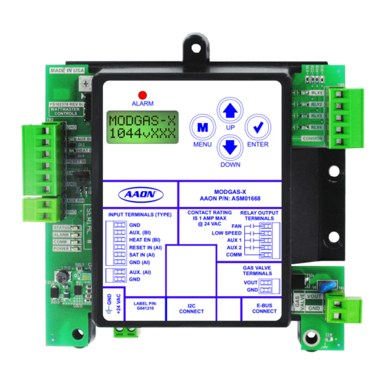
Figure 13: MODGAS-X Module
Appendix C: Maxitrol ® Valves
MAXITROL ® Stepper Valve Types
Figure 14: Two-Wire 0-20 Volt Reverse-Acting MAXITROL ® Selectra Stepper Valve
Figure 15: Four-Wire 0-10 Volt Directing-Acting MAXITROL ® EXA STAR Stepper Valve
Advertisement
Quick Links
1
Sequence of Operation
2
Operating Modes
3
Troubleshooting
Download this manual
MODGAS-X Module
Technical Guide
Table of
Contents
Previous
Page
Next
Page
1
2
3
4
5
Advertisement
Table of Contents
Need help?
Do you have a question about the MODGAS-X and is the answer not in the manual?
Ask a question
Questions and answers
Related Manuals for AAON MODGAS-X
Control Unit AAON MODGAS-XWR2 Technical Manual
(43 pages)
Control Unit AAON MHGRVX-A2 Technical Manual
(35 pages)
Control Unit AAON MODGAS-XWR2-B Technical Manual
(44 pages)
Control Unit AAON RSMD2R Technical Manual
(42 pages)
Control Unit AAON RSMZ Technical Manual
(40 pages)
Control Unit AAON RSMD-CM Technical Manual
Refrigerant system module for digital compressors with condenser fans with microchannel coils (43 pages)
Control Unit AAON HP2C2 Technical Manual
Two condenser head pressure ii module (17 pages)
Control Unit AAON RSMD Technical Manual
(42 pages)
Control Unit AAON RSMD Series Technical Manual
(37 pages)
Control Unit AAON RSMVQ2R Technical Manual
Refrigerant system module (36 pages)
Control Unit AAON RSMV ASM01686 Technical Manual
Refrigerant system module for vfd compressors (32 pages)
Control Unit AAON SS1068 Quick Start Manual
Modular system manager sd (20 pages)
Control Unit AAON RSMVQ Technical Manual
(36 pages)
Control Unit AAON RSM-DEV1 Technical Manual
(40 pages)
This manual is also suitable for:
Asm01668
Table of Contents
Save PDF
Print
Rename the bookmark
Delete bookmark?
Delete from my manuals?
Login
Sign In
OR
Sign in with Facebook
Sign in with Google
Upload manual
Upload from disk
Upload from URL


Need help?
Do you have a question about the MODGAS-X and is the answer not in the manual?
Questions and answers