Table of Contents
Advertisement
Advertisement
Table of Contents
Troubleshooting

Related Manuals for AAON HP2C2


Summary of Contents for AAON HP2C2
- Page 1 Two Condenser Head Pressure II Module Technical Guide...
- Page 2 HP2C2 REVISION LOG REVISION AND DATE CHANGE Rev. E, April 1, 2015 previous version added note the HSSC cable is no longer supplied with this module, updated HP2C2 Rev. F, September 1, 2022 labels HP2C2 PARTS REFERENCE PART DESCRIPTION PART NUMBER...
-
Page 3: Table Of Contents
TABLE OF CONTENTS OVERVIEW ..............................3 Module Overview ..............................4 Mounting and Wiring Considerations ........................5 INSTALLATION & WIRING ........................5 Stand-Alone Wiring ..............................6 E-BUS Controller to Two Condenser Head Pressure II Module Wiring ..............7 E-BUS Controller to Two Condenser Head Pressure II Module Wiring ..............8 Stand-Alone Input Commands .......................... -
Page 4: Overview
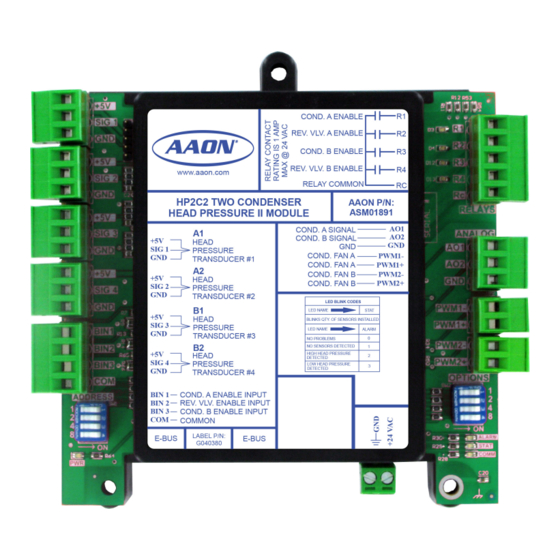
COND. A ENABLE SIG 1 REV. VLV. A ENABLE COND. B ENABLE REV. VLV. B ENABLE www.aaon.com SIG 2 RELAY COMMON HP2C2 TWO CONDENSER AAON P/N: HEAD PRESSURE II MODULE ASM01891 RELAYS COND. A SIGNAL ANALOG SIG 3 COND. B SIGNAL... -
Page 5: Mounting And Wiring Considerations
COND. A ENABLE SIG 1 REV. VLV. A ENABLE COND. B ENABLE REV. VLV. B ENABLE www.aaon.com RELAY COMMON SIG 2 HP2C2 TWO CONDENSER AAON P/N: HEAD PRESSURE II MODULE ASM01891 RELAYS COND. A SIGNAL SIG 3 COND. B SIGNAL... -
Page 6: Stand-Alone Wiring
REV. VLV. A ENABLE Condenser COND. B ENABLE Signal B REV. VLV. B ENABLE www.aaon.com SIG 2 RELAY COMMON COMM HP2C2 TWO CONDENSER AAON P/N: HEAD PRESSURE II MODULE ASM01891 RELAYS COND. A SIGNAL COND. B SIGNAL ANALOG SIG 3... -
Page 7: E-Bus Controller To Two Condenser Head Pressure Ii Module Wiring
REV. VLV. A ENABLE Condenser COND. B ENABLE Signal B REV. VLV. B ENABLE www.aaon.com SIG 2 RELAY COMMON COMM HP2C2 TWO CONDENSER AAON P/N: HEAD PRESSURE II MODULE ASM01891 RELAYS COND. A SIGNAL SIG 3 COND. B SIGNAL ANALOG... -
Page 8: E-Bus Controller To Two Condenser Head Pressure Ii Module Wiring
RELAY 4 RELAY 5 Relay Output Contacts R2 Through R5 May Be User-Configured For The Following: VCM-X MODULAR E-BUS CONTROLLER AAON No.: Orion No.:OE332-23E-VCMX-MOD-A V07150 1 - Heating Stages 2 - Cooling Stages AI1 = SPC (SPACE TEMPERATURE SENSOR) = SAT (SUPPLY AIR TEMPERATURE SENSOR) -
Page 9: Stand-Alone Input Commands
SEQUENCE OF OPERATION Stand-Alone Input Commands General Stand-Alone Input Commands Condenser Fan A On/Off The following inputs and outputs are available on the Two Condenser Head Pressure II Module. See Table 1 below to A 24 volt signal to Binary Input #1 initiates the Condenser Fan A reference the Input/Output Map. -
Page 10: Vcm-X Input Commands And Modes Of Operation
Zone SEQUENCE OF OPERATION Zone VCM-X Input Commands and Modes of Operation Input Commands (VCM-X Connection) Cooling Mode If the Head Pressure Controller has been configured for the Condenser A & B On/Off Reversing Valve to be energized in the Cooling Mode and to Fail Instead of a hard wired input signal to the Condenser Enable to the Heat Mode (Dipswitch 4 is set ON), then the Head Pressure input, the VCM-X Modular Controller, VCM-X WSHP... -
Page 11: Options Dip Switch Settings
SEQUENCE OF OPERATION OPTIONS Dip Switch Settings Head Pressure Setpoint OPTIONS Dip Switch Settings Air Cooled Condenser Water Cooled Condenser Binary Value R410-A R410-A 340 (DEFAULT) 235 (DEFAULT) Table 2: OPTIONS Dip Switch/Head Pressure Setpoint Settings for Stand-Alone Operation ADDRESS Dip Switch 1 Settings Switch 1 Default SP Description of Default Head Pressure Setpoint... -
Page 12: Options Dip Switch Settings
Zone Zone SEQUENCE OF OPERATION Zone Zone OPTIONS Dip Switch Settings ADDRESS Dip Switch 2 Settings Switch 2 Description Set to OFF if Using only (1) Head Pressure Module or if this is Module 1 when Using (2) Head Pressure Modules. -
Page 13: Head Pressure Module Valve/Fan Position Troubleshooting
TROUBLESHOOTING Head Pressure Module Valve / Fan Position Troubleshooting Head Pressure Module Valve/Fan PWM- 0 volts = 100% fan speed Position Troubleshooting 6 volts = 75% fan speed 12 volts = 50% fan speed 18 volts = 25% fan speed If configured for Water valve: 20.4 volts = 15% fan speed Above 20.4 volts = 0% fan speed... -
Page 14: Troubleshooting For Stand-Alone Mode
Good sensors Measure DC connected Volts between SIGx & GND for all sensors Compare readings Is There to chart “PWR” 24VAC Testpoint ? Call AAON Technical Verify Call WattMaster Support Technical Incoming Support Power Fan Speed Heat Enable “STAT” LED or Water Valve A &... -
Page 15: Pressure Transducer Troubleshooting And Leds
TROUBLESHOOTING Pressure Transducer Troubleshooting and LEDs Using LEDs to Verify Operation Pressure Transducer Troubleshooting The Two Condenser Head Pressure II Module is equipped If you suspect there is a problem with the Module related to with LEDs that can be used to verify operation and perform pressure transducer measurements, reference Table 7 below. -
Page 16: Led Diagnostics
Zone TROUBLESHOOTING Zone LED Diagnostics LED Diagnostics ‚ Module LEDs When the Two Condenser Head Pressure II “PWR” LED: Module is powered up, the PWR LED (located below the address - This LED will light up whenever Condenser A Enable “R1”... - Page 17 PARTS: For replacement parts, please contact your local AAON Representative. 2425 South Yukon Ave • Tulsa, OK • 74107-2728 Ph: (918) 583-2266 • Fax: (918) 583-6094 AAON P/N: V22100, Rev. F Created in the USA • Copyright September 2022 • All Rights Reserved...
Need help?
Do you have a question about the HP2C2 and is the answer not in the manual?
Questions and answers