Table of Contents
Advertisement
Quick Links
Advertisement
Table of Contents

Related Manuals for AAON RSMV ASM01686


Summary of Contents for AAON RSMV ASM01686
- Page 1 RSMV Technical Guide...
- Page 2 AAON AAON P/N: V87390, Rev. 01D 2425 South Yukon Ave. © February 2021 AAON Inc. All rights reserved throughout Tulsa, OK 74107-2728 the world. www.aaon.com AAON is a registered trademark of AAON, Inc., Tulsa, OK.
-
Page 3: Table Of Contents
TABLE OF CONTENTS OVERVIEW ........................5 RSMV Overview ..............................5 RSMV Dimensions ..............................6 INSTALLATION AND WIRING ..................7 Electrical and Environmental Requirements ......................7 WIRING ..........................8 RSMV Inputs Wiring ..............................8 RSMV Outputs Wiring ............................. 9 INPUTS AND OUTPUTS ....................10 RSMV Module Inputs/Outputs Map ........................ - Page 4 FIGURES AND TABLES FIGURES Figure 1: Refrigerant System Module Dimensions ....................6 Figure 2: RSMV Inputs Wiring ........................... 8 Figure 3: RSMV Outputs Wiring ..........................9 Figure 4: LCD Display and Navigation Keys ......................14 Figure 5: RSMV LED Locations ..........................22 Figure 6: Prism 2 Condenser Configuration - Single Condenser Per Module ............
-
Page 5: Overview
Supply Air Temperature during Cooling Mode. During Dehumidification Mode, it controls the The RSMV is connected to the VCCX2 Controller or other AAON Compressors to the Suction (Saturation) Temperature Unit Controller. Up to 4 RSMV’s can be connected, depending on Setpoint. -
Page 6: Rsmv Dimensions
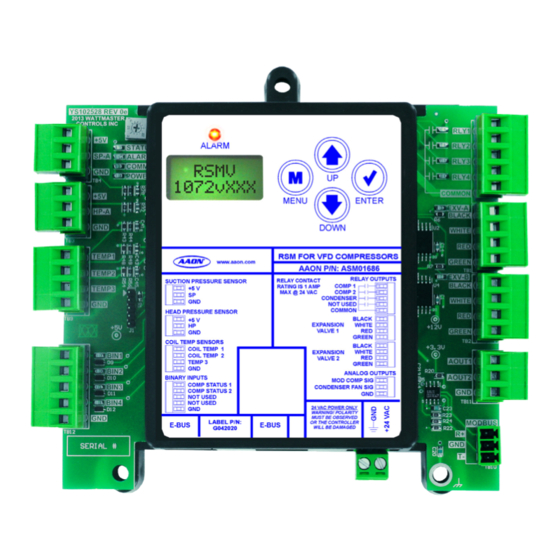
OVERVIEW RSMV Dimensions ALARM MENU ENTER DOWN RSM FOR VFD COMPRESSORS www.aaon.com AAON P/N: ASM01686 RELAY OUTPUTS RELAY CONTACT SUCTION PRESSURE SENSOR COMP 1 RATING IS 1 AMP +5 V MAX @ 24 VAC COMP 2 CONDENSER NOT USED COMMON... -
Page 7: Installation And Wiring
The Main Unit Controller and Modules are 2. All 24 VAC wiring must be connected so that all ground factory installed and wired at the AAON factory. Some of the wires remain common. Failure to follow this procedure... -
Page 8: Wiring
MENU ENTER ENSOR (BY OTHERS) DOWN TEMP1 RSM FOR VFD COMPRESSORS www.aaon.com TEMP2 AAON P/N: ASM01686 RELAY OUTPUTS COIL (SUCTION LINE) RELAY CONTACT SUCTION PRESSURE SENSOR COMP 1 RATING IS 1 AMP +5 V MAX @ 24 VAC COMP 2 TEMP. -
Page 9: Rsmv Outputs Wiring
RLY3 CONDENSER ENABLE COMM MENU ENTER DOWN EXPANSION VALVE 1 RSM FOR VFD COMPRESSORS www.aaon.com AAON P/N: ASM01686 RELAY OUTPUTS RELAY CONTACT SUCTION PRESSURE SENSOR RATING IS 1 AMP COMP 1 +5 V EXPANSION MAX @ 24 VAC COMP 2... -
Page 10: Inputs And Outputs
INPUTS AND OUTPUTS RSMV Module Inputs/Outputs Map Inputs/Outputs Map See Table 2, below for the RSMV inputs and outputs. RSMV Inputs/Outputs Analog Inputs Suction Pressure Sensor (SP) Head Pressure Sensor (HP) Coil (Suction Line) Temperature Sensor 1 (TEMP1) Coil (Suction Line) Temperature Sensor 2 (TEMP2) Binary Inputs Compressor Status 1 (BIN1) Compressor Status 2 (BIN2) -
Page 11: Rsmv Inputs And Outputs
INPUTS AND OUTPUTS RSMV Inputs and Outputs RSMV - Inputs & Outputs BIN1 - Compressor Status 1 When this wet contact input closes, a 24 volt signal to Binary Input +5V VDC Power #1 indicates that Compressor 1 is running. Typically, the source for this is a relay output from the compressor VFD drive. -
Page 12: Sequence Of Operations
SEQUENCE OF OPERATIONS Cooling Mode and Dehumidification Operation Cooling Mode Operation Dehumidification Operation In the Cooling Mode, as the Supply Air Temperature (SAT) rises Once in Dehumidification Mode, units with fixed compressors above the Active SAT Cooling Setpoint, the compressors will stage will activate the compressors to maintain the Evaporator Coil on and modulate to maintain the Active Evaporator Coil Suction Suction (Saturated) Temperature Setpoint. -
Page 13: Electronic Expansion Valve Operation And Head Pressure Control
SEQUENCE OF OPERATIONS Electronic Expansion Valve Operation and Head Pressure Control Electronic Expansion Valve (EXV) Operation If EXV’s are being used, a Coil (Suction Line) Temperature Sensor will measure the Coil (Suction Line) Temperature after each Evaporator Coil line for each compressor, and this sensor will be connected to an RSMV Module. -
Page 14: Rsmv Lcd Screens
RSMV LCD SCREENS LCD Display Screen and Navigation Keys LCD Display Screen & Navigation Keys Navigation Key Function The LCD display screens and buttons allow you to view status and alarms, and enable force modes. See Figure 4, below and refer to MENU Use the MENU key to move through screens Table 3 for descriptions. -
Page 15: Main Screens Map And Rsmv Module Screens
RSMV LCD SCREENS Main Screens Map and RSMV Module Screens RSMV Main Screens Map RSMV Module Screens Refer to the following map when navigating through the LCD Main Refer to the following map when navigating through the RSMV Screens. To scroll through the screens, press the button. -
Page 16: System Status Screens
RSMV LCD SCREENS System Status Screens COMP A1-D1 OFF/ MODULATING % #OF EXVs COMPRESSOR A1, B1, C1, D1 (based on board address) OFF / MOD POSITION # OF EXPANSION VALVES OFF: Compressor is off. MODULATING PERCENTAGE: 0-100% COMP A1= COMP A2-D2 MOD OR FIXED ON/OFF COMPRESSOR A1 STATUS... -
Page 17: Sensor Status And Setpoint Status Screens
RSMV LCD SCREENS Sensor Status and Setpoint Status Screens Sensor Status Screens Refer to the following map when navigating through the Sensor Status Screens. From the SENSOR STATUS Screen, press to scroll through the screens. COIL 2 <ENTER> XXºF SENSOR COIL TEMPERATURE 2 READING FROM STATUS TEMPERATURE SENSOR INPUT... -
Page 18: Setpoint Status Screens And Alarms Screen
RSMV LCD SCREENS Setpoint Status Screens and Alarms Screen COMPRESSOR (COMP) A2 FAILURE: This alarm will occur if the compressor fails to run 45 seconds after the relay is activated or if the LOW SUCT signal is lost after activation. This will cause an alarm and will shut down 95 psi the compressor (relay). -
Page 19: Alarm History And Protected Screens
RSMV LCD SCREENS Alarm History and Protected Screens Alarm History Screens Protected Screens Map The ALARM HISTORY Screen displays past alarms, if any, and how Refer to the following map when navigating through the LCD long ago the last of each type occurred. From the ALARM HISTORY Protected Screens. -
Page 20: Diagnostic Screens
RSMV LCD SCREENS Diagnostic Screens Diagnostic Screens HP-A VLT Refer to the following map when navigating through the Diagnostic X.XX Screens. From the DIAGNSTC Screen, press to scroll <ENTER> through the screens. HEAD PRESSURE SENSOR VOLTAGE Displays the current voltage of the Head Pressure Sensor. DIAGNSTC BIN1 - BIN4 ON/OFF... -
Page 21: Diagnostic, Alarm Count, And Address Screens
RSMV LCD SCREENS Diagnostic, Alarm Count, and Address Screens ALARM COUNTS Screens FORCE From the ALARM COUNTS Screen, press to scroll <ENTER> MODE ON/OFF through the screens. Each screen will display the name of the alarm and how many times the alarm has occurred since you last cleared the alarms. -
Page 22: Troubleshooting
- This LED will light up to indicate that 24 VAC power has been applied to the controller. ALARM MENU ENTER DOWN RSM FOR VFD COMPRESSORS www.aaon.com AAON P/N: ASM01686 RELAY OUTPUTS RELAY CONTACT SUCTION PRESSURE SENSOR RATING IS 1 AMP COMP 1 +5 V MAX @ 24 VAC... -
Page 23: Suction Pressure Transducer Testing
TROUBLESHOOTING Suction Pressure Transducer Testing Suction Pressure Suction Pressure Transducer Testing for R410A Transducer Coil Refrigerant Pressure – Temperature – Voltage Chart for R410A Refrigerant The Evaporator Coil Temperature is calculated by converting the Suction Pressure to Temperature. The Suction Pressure is obtained by using the Suction Pressure Transducer, which is connected into the Suction Line of the Compressor. -
Page 24: Temperature Sensor Testing
TROUBLESHOOTING Temperature Sensor Testing Sensor Voltage and Resistance Thermistor Sensor Testing Instructions Use the resistance column to check the thermistor sensor while The following sensor voltage and resistance table is provided to disconnected from the controllers (not powered). aid in checking sensors that appear to be operating incorrectly. See Table 5, below. -
Page 25: Head Pressure Transducer
TROUBLESHOOTING Head Pressure Transducer If you suspect there is a problem related to the head pressure transducer, measurements can be taken at the HP terminal. See Table 6, below. Head Pressure Transducer Chart Voltage Pressure Voltage Pressure Table 6: Head Pressure Transducer Chart RSMV Technical Guide... -
Page 26: Appendix A: Condenser Options
APPENDIX A: CONDENSER OPTIONS Single Condenser Configuration Single Condenser Per One Module Modular Service Tool Screen In Single Condenser Per One Module wiring configuration, the RSMV Condenser Options Condenser Signal is wired to AO2 and the Condenser Relay (RLY3) Configuration Screen is enabled. -
Page 27: Figure 7: Prism 2 Condenser Configuration - Single Condenser Per Two Modules
APPENDIX A: CONDENSER OPTIONS Single Condenser Configuration Single Condenser Per Two Modules Modular Service Tool Screen In Single Condenser Per Two Modules wiring configuration, if using RSMV Condenser Options 2 modules, the Condenser Signal is wired to AO2 on the 1st module Configuration Screen but not the 2nd module and the Condenser Relay (RLY3) is enabled on the 1st module but not the 2nd module. -
Page 28: Figure 8: Prism 2 Condenser Configuration - Single Condenser For Three Modules
APPENDIX A: CONDENSER OPTIONS Single Condenser Configuration Single Condenser for Three Modules Modular Service Tool Screen In Single Condenser for Three Modules wiring configuration, the RSMV Condenser Options Condenser Signal is wired to AO2 on the 1st module but not the Configuration Screen 2nd &... -
Page 29: Figure 9: Prism 2 Condenser Configuration - Single Condenser For Four Modules
APPENDIX A: CONDENSER OPTIONS Single Condenser Configuration Single Condenser Per Four Modules Modular Service Tool Screen In Single Condenser Per Four Modules wiring configuration, the RSMV Condenser Options Condenser Signal is wired to AO2 on the 1st module but not the 2nd, Configuration Screen 3rd, or 4th modules and the Condenser Relay (RLY3) is enabled on the 1st module but not the 2nd, 3rd, or 4th modules. -
Page 30: Appendix B: Prism 2 System Configuration
APPENDIX B: PRISM 2 SYSTEM CONFIGURATION System Configuration General Refer to Figure 10, below in setting RSMV configuration options. The following features are not compatible with the RSMV: • RSMV-Q Tonnage Selection • Two Step Timing Compressor Configurations Make selection from the drop-down menu for Module A, see Figure 11. - Page 31 NOTES RSMV Technical Guide...
- Page 32 RSMV Technical Guide V87390 · Rev. 01D · 210204 AAON Factory Technical Support: 918-382-6450 techsupport@aaon.com AAON Controls Support: 866-918-1100 Monday through Friday, 7:00 AM to 5:00 PM Central Standard Time Controls Support website: www.aaon.com/controlstechsupport NOTE: Before calling Technical Support, please have the model and serial number of the unit available.
Need help?
Do you have a question about the RSMV ASM01686 and is the answer not in the manual?
Questions and answers