Table of Contents
Advertisement
Quick Links
Advertisement
Table of Contents

Subscribe to Our Youtube Channel
Related Manuals for AAON RSMD2R


Summary of Contents for AAON RSMD2R
- Page 1 RSMD2R Technical Guide...
- Page 2 RSMD2R REVISION LOG REVISION & DATE CHANGE Rev. A, March 15, 2021 Original RSMD2R PARTS REFERENCE PART DESCRIPTION PART NUMBER Refrigerant System Module for Digital Compressors ( RSMD2R) ASM02869 VCCX2 Controller ASM01698 Prism 2 ASM02533 IP Module Kit ASM01902 CommLink 5 ASM01874 EBC E-BUS Cable Assembly E-BUS Power &...
-
Page 3: Table Of Contents
Cooling Mode, Dehumidification, and Head Pressure Control ................12 LCD SCREENS ....................... 13 LCD Display Screen and Navigation Keys ......................13 Main Screens Map and RSMD2R Module Screens ....................14 System Status Screens ............................15 Sensor Status Screens ............................16 Setpoint Status Screens ............................ - Page 4 Single Condenser Per RSMD2R Module Wiring Figure 8: ....................31 Prism 2 Condenser Configuration: Single Condenser Per Module Figure 9: ..............32 Single Condenser Per Two RSMD2R Modules Wiring Figure 10: ..................33 Prism 2 Condenser Configuration: Single Condenser Per Two Modules Figure 11: ............34...
-
Page 5: Overview
3. Reheat is present on the second circuit only. The RSMD2R is connected to the VCCX2 Controller. Up to four RSMD2R’s can be connected, depending on the size of the system. There are two E-BUS Expansion Ports which allow the use of communicating sensors and the E-BUS Modules. -
Page 6: Rsmd2R Dimensions
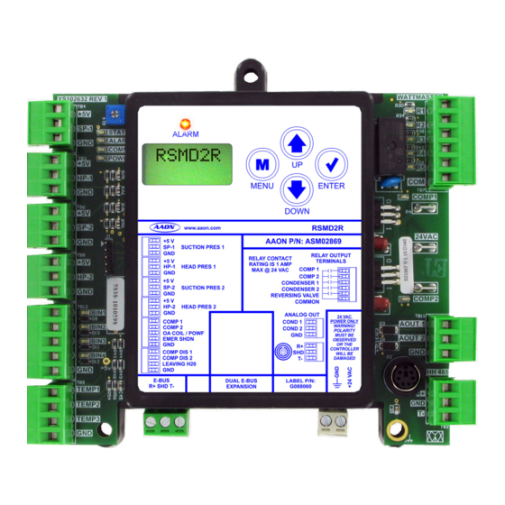
EMER SHDN OBSERVED OR THE CONTROLLER COMP DIS 1 WILL BE COMP DIS 2 DAMAGED LEAVING H20 E-BUS DUAL E-BUS LABEL P/N: R+ SHD T- G088060 EXPANSION 4.10 0.75 0.74 0.52 1.50 1.50 1.33 Figure 1: RSMD2R Dimensions RSMD2R Technical Guide... -
Page 7: Installation And Wiring
The main unit controller and modules are 2. All 24 VAC wiring must be connected so that all factory installed and wired at the AAON factory. Some of the ground wires remain common. Failure to follow this following information may not apply to your installation if it procedure can result in damage to the controller and was pre-wired at the factory. -
Page 8: Wiring
The RSMD2R is connected to the VCCX2 Controller. Up to Coil (Saturated) Temperature Setpoint. In Cooling mode, four RSMD2R’s can be connected, depending on the size of the the VCCX2 resets the Suction Coil (Saturated) Temperature system. There are two E-BUS Expansion Ports which allow the Setpoint to maintain a given Supply Air Temperature Setpoint. -
Page 9: Rsmd2R Outputs Wiring
18-30 a split system. 3 Y1 Belimo actuator wiring Size transformer for Line Voltage shown. Consult factory for correct total load. RSMD2R = 18 VA other manufacturer wiring instructions. Figure 3: RSMD2R Outputs Wiring RSMD2R Technical Guide... -
Page 10: Inputs And Outputs
INPUTS AND OUTPUTS RSMD2R Module Inputs/Outputs Map Inputs/Outputs Map See Table 2, this page for the RSMD2R inputs and outputs. REFRIGERATION SYSTEM MODULE FOR DIGITAL COMPRESSORS Analog Inputs Suction Pressure 1 Sensor (SP-1) Head Pressure 1 Sensor (HP-1) Suction Pressure 2 Sensor (SP-2) -
Page 11: Rsmd2R Inputs And Outputs
INPUTS AND OUTPUTS RSMD2R Inputs and Outputs RSMD2R - Inputs & Outputs BIN3 - Outside Coil Temperature / Proof of Water Flow Status +5V VDC Power This input can be used for the following two options: This output is a 5 VDC output that supplies power to the Suction Air to Air Heat Pump Pressure Transducers. -
Page 12: Sequence Of Operations
Multiple RSMD2Rs are needed when there are more than two maintain the Coil Temperature Setpoint. compressors. If the RSMD2R has two Digital Compressors, the 1st Compressor In units with one digital and one fixed compressors, if the digital will be locked at 100% and the 2nd Compressor will modulate. -
Page 13: Lcd Screens
Use this key to adjust setpoints and change configurations. ENTER Use the ENTER key to navigate through the Main Menu Screen categories. MENU ENTER DOWN Table 3: Navigation Key Functions Figure 4: LCD Display and Navigation Keys RSMD2R Technical Guide... -
Page 14: Main Screens Map And Rsmd2R Module Screens
LCD SCREENS Main Screens Map and RSMD2R Module Screens RSMD2R Main Screens Map RSMD2R Module Screens Refer to the following map when navigating through the LCD Refer to the following map when navigating through the Main Screens. To scroll through the screens, press the RSMD2R Screens. -
Page 15: System Status Screens
WATERSIDE ECONOMIZER BYPASS VALVE COMP A1-B1 CLOSED or MOD POSITION OFF/ CLOSED: Valve is closed. MODULATING PERCENTAGE: 0-100% MODULATING % COMPRESSOR A1, B1 (based on board address) OFF / MOD POSITION OFF: Compressor is off. MODULATING PERCENTAGE: 0-100% RSMD2R Technical Guide... -
Page 16: Sensor Status Screens
PRESSURE 2 INPUT HEAD PRESSURE 1 READING FROM INPUT If configured for Water Source Heat Pump SUCTION 2 H2O TEMP XXX PSI XX DEG SUCTION PRESSURE 2 READING FROM INPUT WATER TEMPERATURE READING FROM LEAVING WATER TEMPERATURE SENSOR RSMD2R Technical Guide... -
Page 17: Setpoint Status Screens
FOLLOWING TWO SCREENS WILL DISPLAY DEFR INT 30 MIN FAN ON XX PSI DEFROST INTERVAL SETPOINT STATUS Default is 30 minutes. HEAD PRESSURE HEADING WHEN FAN CYCLE IS ON FAN OFF XX PSI HEAD PRESSURE READING WHEN FAN CYCLE IS OFF RSMD2R Technical Guide... -
Page 18: Alarms Screens
This alarm indicates that EBUS SLAVE (SLV) TIMEOUT: by lowering compressor modulation percentage. communication has been lost between the RSMD2R and the Main controller or other E-BUS modules that may be connected. This This alarm will occur if the COMPRESSOR (COMP1) 1 FAULT:... - Page 19 COMPRESSOR (COMP) 1 or 2 LOCKOUT: occurs five times within a four-hour period, the compressor will be locked out. Must cycle power to RSMD2R to clear the alarm. • If a circuit’s Suction Pressure falls below the Low Suction Pressure Setpoint for longer than one minute twice within a two hour window, the compressor on that circuit will be locked out.
-
Page 20: Alarm History And Protected Screens
So, if power is lost, the alarms will clear. DIAGNSTC Protected Screens Map Refer to the following map when navigating through the LCD Protected Screens. From the RSMD2R Screen, press <ENTER> twice to get to the Software Screen. Then hold the button <UP>... -
Page 21: Configuration And Diagnostic Screens
Displays the numbers of times the board has been reset due to Displays the current voltage of the Suction Pressure Sensor 2. watchdog timer overview. HP-2 VLT X.XX HEAD PRESSURE SENSOR 2 VOLTAGE Displays the current voltage of the Head Pressure Sensor 2. RSMD2R Technical Guide... -
Page 22: Diagnostic Screens
FORCE MODE AOUT-2 V Displays the current status of Force Mode. Values are ON/OFF. 1.0-10.0 CONDENSER SIGNAL 2 FORCE 0.0 to 10.0 = Active Force Mode Press the <UP> or <DOWN> buttons to increase and decrease the value. RSMD2R Technical Guide... -
Page 23: Alarm Counts And Address Screen
Configure the address according to which refrigerant circuit this module represents—1=A, 2=B, 3=C, 4=D Number in parentheses is E-BUS address. Module 1’s address is 152, Module 2’s address is 153, Module 3’s address is 154, Module 4’s address is 155 RSMD2R Technical Guide... -
Page 24: Troubleshooting
Operation Binary Input LEDs The RSMD2R is equipped with LEDs that can be used to verify - This green LED will light up when Compressor Status operation and perform troubleshooting. There are LEDs for BIN1 1 contact is closed. -
Page 25: Suction Pressure Transducer Testing
RSMD2R Module(s) must be powered for this test. Read voltage with a meter set on DC volts. Place the positive lead 21.19 -6.1 80.94 from the meter on the SP1/SP2 terminal located on the RSMD2R 24.49 -4.4 87.16 Module(s) terminal block. Place the negative lead from the meter 27.80... -
Page 26: Copeland ® Discharge Thermistor Temperature Sensor Testing
1.80 0.76 56.16 4.24 1.59 0.68 45.81 4.10 1.39 0.61 37.58 3.94 1.25 0.55 30.99 3.77 1.12 0.50 25.68 3.59 1.01 0.45 21.40 3.40 0.92 0.42 17.91 3.20 0.83 0.38 15.07 3.00 Table 5: Discharge Thermistor Temperature/Resistance RSMD2R Technical Guide... -
Page 27: Temperature Sensor Testing
3317 1.246 12191 2.746 57.2 3015 1.159 20.6 11906 2.717 2743 1.077 21.1 11652 2.691 62.7 2502 1.001 21.7 11379 2.661 65.6 2288 0.931 Table 6: 0-5V Temperature Sensor - Voltage & Resistance for Type III Sensors RSMD2R Technical Guide... -
Page 28: Head Pressure Transducer
If you suspect there is a problem related to the head pressure transducer, measurements can be taken at the HP terminal. See Table 7, this page. Head Pressure Transducer Chart Voltage Pressure Voltage Pressure Table 7: Head Pressure Transducer Chart RSMD2R Technical Guide... -
Page 29: Appendix A: Condenser Options
R+ SHD T- EXPANSION G088060 Connects to VCCX2 Loop Communications connector when used on 18-30 a split system. Size transformer for Line Voltage correct total load. RSMD2R = 18 VA Figure 6: Default: Two Condenser RSMD2R Module Wiring RSMD2R Technical Guide... -
Page 30: Figure 7: Prism 2 Condenser Configuration: Default Two Condenser Operations
RSMD2R CONFIGURATION Condenser Options 2 Cond per RSMD2R USE < or > TO CHANGE Select the “2 Condensers per RSMD2R” option on the above Hand Held Service Tool Screen. HVAC Unit Application The Two Condenser per RSMD2R configuration is used with the following HVAC units: •... -
Page 31: Single Condenser Per Module
R+ SHD T- EXPANSION G088060 Connects to VCCX2 Loop Communications connector when used on 18-30 a split system. Size transformer for Line Voltage correct total load. RSMD2R = 18 VA Figure 8: Single Condenser Per RSMD2R Module Wiring RSMD2R Technical Guide... -
Page 32: Figure 9: Prism 2 Condenser Configuration: Single Condenser Per Module
Single Condenser Per Module Figure 9: Prism 2 Condenser Configuration: Single Condenser Per Module RSMD2R Main Configuration Screen #2 - Condenser Options Select the “1 Condenser for 1 RSMD2R” option on the above Hand Held Service Tool Screen. RSMD2R CONFIGURATION Condenser Options 1 Cond for 1 RSMD2R USE <... -
Page 33: Single Condenser Per Two Modules
Note: If there are four modules, Size transformer for 1 and 3 match and 2 and 4 Line Voltage correct total load. match. RSMD2R = 18 VA Figure 10: Single Condenser Per Two RSMD2R Modules Wiring RSMD2R Technical Guide... -
Page 34: Figure 11: Prism 2 Condenser Configuration: Single Condenser Per Two Modules
APPENDIX A: CONDENSER OPTIONS Single Condenser Per Two Modules Figure 11: Prism 2 Condenser Configuration: Single Condenser Per Two Modules RSMD2R Main Configuration Screen #2 - Condenser Options RSMD2R CONFIGURATION Condenser Options 1 Cond for 2 RSMD2Rs USE < or > TO CHANGE Select the “1 Condenser for 2 RSMD2Rs”... -
Page 35: Single Condenser For Three Modules
Note: If there are four modules, Size transformer for 1 and 3 match and 2 and 4 Line Voltage correct total load. match. RSMD2R = 18 VA Figure 12: Single Condenser for Three RSMD2R Modules Wiring RSMD2R Technical Guide... -
Page 36: Figure 13: Prism 2 Condenser Configuration: Single Condenser For Three Modules
APPENDIX A: CONDENSER OPTIONS Single Condenser Per Three Modules Figure 13: Prism 2 Condenser Configuration: Single Condenser for Three Modules RSMD2R Main Configuration Screen #2 - Condenser Options RSMD2R CONFIGURATION Condenser Options 1 Cond for 3 RSMD2Rs USE < or > TO CHANGE Select the “1 Condenser for 3 RSMD2Rs”... -
Page 37: Two Condensers Per Two Modules
DUAL E-BUS LABEL P/N: R+ SHD T- EXPANSION G088060 Connects to VCCX2 Loop Communications connector when used on 18-30 a split system. Size transformer for Line Voltage correct total load. RSMD2R = 18 VA Figure 14: A1/B1 Wiring RSMD2R Technical Guide... -
Page 38: Figure 15: A2/B2 Wiring
DUAL E-BUS LABEL P/N: R+ SHD T- EXPANSION G088060 Connects to VCCX2 Loop Communications connector when used on 18-30 a split system. Size transformer for Line Voltage correct total load. RSMD2R = 18 VA Figure 15: A2/B2 Wiring RSMD2R Technical Guide... -
Page 39: Figure 16: Prism 2 Condenser Configuration: A1/B1 And A2/B2 Condenser Configuration
APPENDIX A: CONDENSER OPTIONS Two Condensers Per Two Modules Figure 16: Prism 2 Condenser Configuration: A1/B1 and A2/B2 Condenser Configuration RSMD2R Main Configuration Screen #2 - Condenser Options RSMD2R CONFIGURATION Condenser Options 2 Cond for 2 RSMD2Rs USE < or > TO CHANGE Select the “2 Condensers for 2 RSMD2Rs”... -
Page 40: On/Off Condenser Options
Compressors. This can also be selected when No Head Pressure Control is required. Select this option if the Condenser Fan cycles On/Off based on the Fan Cycle Head Pressure Setpoints. Figure 17: Prism 2 Condenser Configuration: ON/OFF Condenser Options RSMD2R Technical Guide... - Page 41 NOTES RSMD2R Technical Guide...
- Page 42 RSMD2R Technical Guide G088350 · Rev. A · 210315 AAON Factory Technical Support: 918-382-6450 techsupport@aaon.com AAON Controls Support: 866-918-1100 Monday through Friday, 7:00 AM to 5:00 PM Central Standard Time Controls Support website: www.aaon.com/controlstechsupport NOTE: Before calling Technical Support, please have the model and serial number of the unit available.
Need help?
Do you have a question about the RSMD2R and is the answer not in the manual?
Questions and answers