Table of Contents
Advertisement
Quick Links
Advertisement
Table of Contents

Related Manuals for AAON RSMZ


Summary of Contents for AAON RSMZ
- Page 1 RSMZ Technical Guide...
- Page 2 All manuals are also available for download from www.aaon.com/controlsmanuals. AAON AAON P/N: G081900, Rev. A 2425 South Yukon Ave. Copyright June 2021 © AAON. All rights reserved Tulsa, OK 74107-2728 throughout the world. www.aaon.com AAON® and AAONAIRE® are registered trademarks of Factory Technical Support Phone: 918-382-6450 AAON, Inc., Tulsa, OK.
-
Page 3: Table Of Contents
RSMZ Module and Subcool Monitor Input/Output Maps ..................8 WIRING ..........................9 RSMZ Inputs Wiring - Modules 1, 2, 4, and 5 ......................9 RSMZ Outputs Wiring - Modules 1, 2, 4, and 5 ....................10 RSMZ Inputs Wiring - Modules 3 and 6 .........................11 RSMZ Outputs Wiring - Modules 3 and 6 ...................... - Page 4 FIGURES AND TABLES FIGURES RSMZ Dimensions Figure 1: ..............................6 RSMZ Inputs Wiring - Modules 1, 2, 4, and 5 Figure 2: .......................9 RSMZ Outputs Wiring - Modules 1, 2, 4, and 5 Figure 3: ....................10 RSMZ Inputs Wiring - Modules 3 and 6 Figure 4: .......................
-
Page 5: Overview
The Refrigerant System Module for VFD Compressors (RSMZ) monitors and controls one refrigeration circuit of the HVAC unit. The RSMZ is used on RZ units and on RN-E units with Danfoss compressors. The module is designed for R410-A refrigerant. The RSMZ is connected to an AAON unit controller. Three or six RSMZ Modules can be connected, depending on the size of the system. -
Page 6: Rsmz Dimensions
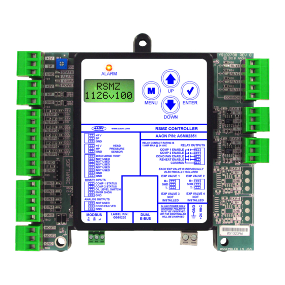
24 VAC POWER ONLY BIN4 WARNING! POLARITY MUST BE OBSERVED LABEL P/N: OR THE CONTROLLER MODBUS DUAL WILL BE DAMAGED G050220 E-BUS AOUT1 AOUT2 4.10 Note: All Dimensions are in inches. Note: Depth is 1.50 inches. Figure 1: RSMZ Dimensions RSMZ Technical Guide... -
Page 7: Installation And Wiring
Please carefully read and apply the following information when wiring the unit controller, RSMZ, and any associated module. Correct wiring of the AAON unit controller and its modules is 1. All wiring is to be in accordance with local and the most important factor in the overall success of the controller national electrical codes and specifications. -
Page 8: Rsmz Module And Subcool Monitor Input/Output Maps
RSMZ Module and Subcool Monitor Input/Output Maps Input/Output Maps SUBCOOL MONITOR MODULE See Table 2, this page for the RSMZ Module inputs and outputs, Analog Inputs Table 3, this page for Subcool Monitor Module inputs and Liquid Line Pressure Transducer 1 (SP-1) outputs, and Table 4, this page for the Reheat Expansion Module inputs and outputs. -
Page 9: Wiring
The RSMZ monitors and controls one refrigeration circuit of the contacts (connected to 24 VAC). See Figure 2, this page for HVAC unit. The RSMZ is used on RZ units and on RN-E units RSMZ input wiring for modules 1, 2, 4, and 5. -
Page 10: Rsmz Outputs Wiring - Modules 1, 2, 4, And 5
AOUT2 18-30 Size transformer for correct total load. RSMZ = 18 VA Line Voltage Danfoss VFD Connect to AAON unit Terminals controller and next RSMZ Figure 3: RSMZ Outputs Wiring - Modules 1, 2, 4, and 5 RSMZ Technical Guide... -
Page 11: Rsmz Inputs Wiring - Modules 3 And 6
WIRING RSMZ Inputs Wiring - Modules 3 and 6 RSMZ Input Wiring See Figure 4, this page for RSMZ outputs wiring for modules 3 and 6. Observe Polarity! All boards must be wired WARNING: with GND-to-GND and 24 VAC-to-24 VAC. Failure to observe polarity will result in damage to one or more of the boards. -
Page 12: Rsmz Outputs Wiring - Modules 3 And 6
WIRING RSMZ Outputs Wiring - Modules 3 and 6 RSMZ Output Wiring See Figure 5, this page for RSMZ outputs wiring for modules 3 and 6. Observe Polarity! All boards must be wired WARNING: with GND-to-GND and 24 VAC-to-24 VAC. Failure to observe polarity will result in damage to one or more of the boards. -
Page 13: Reheat Expansion Module
Reheat Expansion Module Wiring Please refer to the MHGRV-X Technical Guide for NOTE: more information. The Reheat Expansion Module connects to the RSMZ Communication Terminal Block. One or two Reheat Expansion Modules are used per system. Observe Polarity! All boards must be wired... -
Page 14: Subcool Monitor Module
R410-A, R22, and R134a refrigerant and can also be configured for the following pressure transducers—250 psi, 500 psi, and 667 psi. The Subcool Monitor Module is connected to the AAON unit controller. One or two Subcool Monitor Modules can be connected, depending on the size of the system. -
Page 15: Sequence Of Operations
RSMZ Module 1 and that module will then share the mode change with the other RSMZ Modules so that all modules will operate in the same mode. If RSMZ Module 1 goes off line for any reason, then DX coil operations will be stopped for the entire unit. -
Page 16: Alarms
Parameter 16-90, alarm bits 16 – 23 operation to determine if any operating failures have occurred. “DNFSALM1”, “B3 ###” These failures (alarms) will be reported to the AAON unit controller which allows them to be monitored via a BACnet ®... -
Page 17: Alarm Faults
The low superheat detection will be ignored for the first two minutes of initial compressor operation. If the superheat drops below 4ºF for two minutes, the compressor signal will be turned off and will be retried after five minutes. RSMZ Technical Guide... -
Page 18: Alarm Lockouts
High Discharge Line Temperature Lockout If a high Discharge Line Temperature fault occurs three times in a two-hour time period, the circuit will be disabled and locked out until the module is reset. RSMZ Technical Guide... -
Page 19: Subcool Monitor Module Operation
The use of the Subcool Monitor Module is optional. Subcooling Sequence The Subcool Monitor Module reads and scales all of its six inputs and calculates the saturated suction and subcooling for each configured circuit. RSMZ Technical Guide... -
Page 20: Lcd Screens
The MENU key cancels editing when in Edit Mode. The screen you were editing will return to its original value and the underscore will disappear. A second press of the MENU key will return you to the Main Menu. Table 6: Editing Key Functions RSMZ Technical Guide... -
Page 21: Rsmz Lcd Screens
RSMZ LCD SCREENS Main Screens Map RSMZ Main Screens Map Press to go to ALARM LOCKOUTS Screens. Refer to the following map when navigating through the RSMZ ALARM Main Screens. To scroll through the screens, press the <MENU> LOCKOUTS button. -
Page 22: Module Screens
RSMZ LCD SCREENS Module Screens RSMZ Module Screens VFD MAX Refer to the following map when navigating through the RSMZ Screens. From the RSMZ Module Screen, press <ENTER> scroll through the screens. MAX SPEED BASED ON UNIT TONNAGE RSMZ 1126v###... -
Page 23: System Status Screens
RSMZ LCD SCREENS System Status Screens System Status Screens C1 MIN RUN Refer to the following map when navigating through the System Status Screens. From the SYSTEM STATUS Screen, press to scroll through the screens. <ENTER> COMPRESSOR 1 MINIMUM RUN TIME... -
Page 24: Sensor And Setpoint Status Screens
RSMZ LCD SCREENS Sensor and Setpoint Status Screens Sensor Status Screens SUPRHEAT XX.X ° Refer to the following map when navigating through the Sensor Status Screens. From the SENSOR MENU Screen, press to scroll through the screens. <ENTER> SUPERHEAT READING FROM TEMPERATURE... -
Page 25: Alarm Warnings And Alarm Faults Screens
RSMZ LCD SCREENS Alarm Warnings and Alarm Faults Screens Alarm Screens ALARM FAULTS If an alarm is present, the ALARM LED above the LCD display will light up red and blink. The Alarms will display and scroll automatically from the ALARMS screen when alarms are present. -
Page 26: Alarm Lockouts
RSMZ LCD SCREENS Alarm Lockouts ALARM LOCKOUTS LOCKOUTS NO LOCKOUTS This will be shown if there are no current lockouts. LOCKOUTS! This will display if there are active lockouts. —Low/unsafe Suction Pressure SUCT PSI LOCKOUT —Low refrigerant oil level LOW OIL LOCKOUT —High Discharge Pressure... -
Page 27: Danfoss Menu Screens
RSMZ LCD SCREENS Danfoss Menu Screens Danfoss Menu Screens COMMAND Refer to the following map when navigating through the Screens. From the DANFOSS MENU Screen, press to scroll <ENTER> through the screens. COMMAND STATUS Command speed to VFD Range: 0-100%... - Page 28 RSMZ LCD SCREENS Danfoss Menu Screens CURRENT CURRENT OA C1 HOURS COMPRESSOR 1 HOURS VFD HRS VFD HOURS MODEL DANFOSS MODEL PART NUMBER RSMZ Technical Guide...
-
Page 29: Subcool Monitor Lcd Screens
Module 1’s address is 169, Module 2’s address is 170. Press to go to ALARMS screens. ALARMS Press to scroll through ALARMS screens. Press to go to SETPOINT screens. SETPOINT MENU Press to scroll through SETPOINT screens. RSMZ Technical Guide... -
Page 30: Circuit Status And Alarm Screens
No Alarms will display if there are no alarms. COMM TIMEOUT PRES # This alarm will display if the Subcool Monitor is not communicating XXX PSIG with the AAON unit controller. LIQUID LINE READING FROM INPUT SATTEMP # XXX.X °... -
Page 31: Setpoint Screens
UNIT ADDRESS Unit Address. Valid range is 1-59. Default is 59. TMPSCALE TEMPERATURE SCALING Fahrenheit or Celsius REFRGRNT REFRIGERANT 410-A, 134a, R22 TRNSDCER PSIG TRANSDUCER PSIG 250, 500, 667 CIRCUITS 1,2,3 NUMBER OF CIRCUITS 1, 2, 3 RSMZ Technical Guide... -
Page 32: Appendix A: Troubleshooting
- If the software is running, this LED will blink STATUS contact is closed. according to what mode the RSMZ is in. See Table 7, this page. - This green LED will light up when the Oil Level Switch BIN3 is closed. -
Page 33: Subcool Monitor Led Diagnostics
- Every time the module receives a valid E-BUS request COMM from the AAON unit controller, this LED will blink on and then off, signifying that it received a valid request and responded. Figure 10: Subcool Monitor LED Locations... -
Page 34: Reheat Expansion Module Led Diagnostics
COMM LED should blink the same, once every second. The COMM LED should blink simultaneously on all modules. POWER LED COMPRESSOR ENABLE LED STATUS LED COMM LED Figure 11: Reheat Expansion Module LEDs RSMZ Technical Guide... -
Page 35: Temperature Sensor Testing
Note: If the voltage is above 5.08 VDC the sensor or wiring is “open.” If the voltage is less than 0.05 VDC, the sensor or wiring is shorted. Table 8: 0-5V Temperature Sensor - Voltage and Resistance for Type III Sensors RSMZ Technical Guide... -
Page 36: Liquid Line And Head Pressure Transducer
Head Pressure Transducer Testing Use the voltage column to check the Head Pressure Transducer while connected to the RSMZ Module. The module must be powered for this test. Read voltage with a meter set on DC volts. Place the positive lead from the meter on the HP input terminal located on the module. -
Page 37: Appendix B: Danfoss Vfd
0-20 Motor Speed Unit RPM (vs. Hz) blue = user must configure from display yellow = set through communications once communications is established green = default but confirm if not working Table 10: Danfoss VFD Parameter Configurations RSMZ Technical Guide... -
Page 38: Appendix C: System Configuration
In Prism 2’s “Configuration 1 Page”, select the radio button for Select Prism 2’s RSMZ module tab selection. In “Single “Check this box for RSMZ modules”, select the radio button Condenser Per Module” wiring configuration, the Condenser for “3 Circuit 1 Sub-Cool” or “6 Circuit 2 Sub-Cool”, and then Signal is wired to AO2 and the Condenser Relay (RLY3) is select the check box for “RSMZ Has Sub-Cooling Module”... - Page 39 NOTES RSMZ Technical Guide...
- Page 40 RSMZ Technical Guide G081900 · Rev. A · 210610 AAON Factory Technical Support: 918-382-6450 techsupport@aaon.com AAON Controls Support: 866-918-1100 Monday through Friday, 7:00 AM to 5:00 PM Central Standard Time Controls Support website: www.aaon.com/controlstechsupport NOTE: Before calling Technical Support, please have the model and serial number of the unit available.
Need help?
Do you have a question about the RSMZ and is the answer not in the manual?
Questions and answers