Table of Contents
Advertisement
Quick Links
Advertisement
Table of Contents

Related Manuals for AAON RSMD-CM


Summary of Contents for AAON RSMD-CM
- Page 1 RSMD-CM Technical Guide...
- Page 2 AAON Part Number: G102430, Rev. A 2425 South Yukon Ave. Copyright December 2021 AAON, Inc. Tulsa, OK 74107-2728 AAON is a registered trademark of AAON, Inc., Tulsa, OK. ® www.aaon.com Copeland Scroll™ is a registered trademark of Emerson Factory Technical Support Phone: 918-382-6450 Electric Co., Sidney, OH...
-
Page 3: Table Of Contents
Two Condensers Per Module (Default) ......................... 31 Single Condenser Per Module ..........................33 Single Condenser Per Two Modules ........................35 Single Condenser for Three Modules ........................37 A1/B1 and A2/B2 Condenser Configuration ......................39 ON/OFF Condenser Options ..........................42 RSMD-CM Technical Guide... - Page 4 Prism 2 Condenser Configuration - A1/B1 and A2/B2 Condenser Configuration Figure 16: .........41 Prism 2 Condenser Configuration - ON/OFF Condenser Options Figure 17: ..............42 TABLES RSMD-CM Module Electrical and Environmental Requirements Table 1: ...............7 RSMD-CM Inputs and Outputs Table 2: ..........................10 Navigation Key Functions Table 3: ............................13...
-
Page 5: Overview
The compressors can be in either a tandem or non-tandem configuration. The module is designed for R410-A refrigerant. The RSMD-CM is for units that match all of the following criteria: 1. One or two circuits. -
Page 6: Dimensions
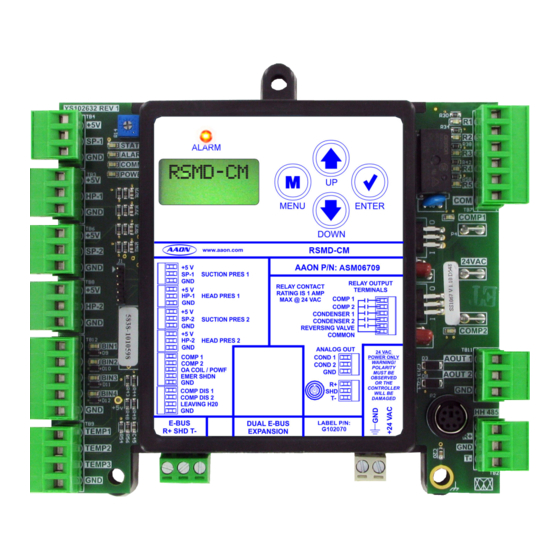
COMP DIS 2 DAMAGED LEAVING H20 HH485 E-BUS DUAL E-BUS LABEL P/N: G102070 R+ SHD T- EXPANSION TEMP1 TEMP2 TEMP3 4.10 0.75 0.74 0.52 1.50 Note: All dimensions are in inches. Figure 1: RSMD-CM Dimensions 1.50 1.33 RSMD-CM Technical Guide... -
Page 7: Installation And Wiring
General Please carefully read and apply the following information when wiring the unit controller, RSMD-CM, and any associated Correct wiring of the AAON controller and its modules is the module. most important factor in the overall success of the installation 1. -
Page 8: Wiring
Inputs Wiring RSMD-CM Wiring Suction Pressure Transducer Wiring The RSMD-CM provides three analog inputs, four binary inputs, The Suction Pressure Transducers must be wired as shown five relays, and two analog outputs. See Figure 2, this page, for in Figure 2, this page. It is typically required for all VCCX2 inputs wiring and Figure 3, page 9, for outputs wiring. -
Page 9: Outputs Wiring
TEMP2 1 COM a split system. TEMP3 3 Y1 18-30 Actuator must be 0-10 VDC with Actuator 24 VAC power. Confirm wiring Line Voltage terminations with manufacturer's wiring instructions. Figure 3: RSMD-CM Outputs Wiring RSMD-CM Technical Guide... -
Page 10: Inputs And Outputs
INPUTS AND OUTPUTS Inputs/Outputs Map Inputs/Outputs Map Inputs and Outputs See Table 2, this page, for the RSMD-CM inputs and outputs. +5V - VDC Power This output is a 5 VDC output that supplies power to the Suction Pressure Transducers. -
Page 11: Inputs And Outputs
If you provide dry contacts, the contact closure will not be recognized. AO1 - Condenser 1 Fan Signal This 0-10 VDC output is used to control/modulate the Condenser 1 Fan /Valve to maintain the Head Pressure Setpoint. RSMD-CM Technical Guide... -
Page 12: Sequence Of Operations
Up Delay, then the fixed compressor will stage on. The digital compressor will then be allowed to modulate as necessary If the RSMD-CM has two digital compressors, the first to maintain the Active Evaporator Coil Suction (Saturation) compressor will be locked at 100% and the second compressor Temperature Setpoint. -
Page 13: Lcd Screens
Use this key to adjust setpoints and change ALARM configurations. ENTER Use the ENTER key to navigate through the Main Menu Screen categories. MENU ENTER DOWN Table 3: Navigation Key Functions Figure 4: LCD Display and Navigation Keys RSMD-CM Technical Guide... -
Page 14: Main Screens Map
ALARMS screens. Press to go to ALARM HISTORY screens. ALARM HISTORY Press to scroll through ALARM HISTORY screens. Press to go to SETPOINT STATUS screens. SETPOINT STATUS Press to scroll through SETPOINT STATUS screens. RSMD-CM Technical Guide... -
Page 15: Module Screens
LCD SCREENS Module Screens Module Screens #COND Refer to the following map when navigating through the CONFIGURED RSMD-CM Screens. From the RSMD-CM Screen, press to scroll through the screens. <ENTER> # OF CONDENSERS CONFIGURED RSMD 1067vxxx COMP A1-B1 FIXED OR DIG... -
Page 16: System Status Screens
DEFROST INTERVAL TIMER COMPRESSOR A2, B2 # of MINUTES (based on board address) ON, OFF, FORCED If configured for Water Source Heat Pump OFF: Compressor is off. ON: Compressor is on. H2O FLOW YES/NO WATER FLOW YES/NO RSMD-CM Technical Guide... -
Page 17: Sensor Status Screens
SUCTION PRESSURE 2 READING FROM INPUT WATER TEMPERATURE READING FROM LEAVING WATER TEMPERATURE SENSOR HEAD PR2 XXX PSI HEAD PRESSURE 2 READING FROM INPUT CALC CT1 XX DEG CALCULATED COIL TEMPERATURE 1 FROM SUCTION PRESSURE 1 INPUT RSMD-CM Technical Guide... -
Page 18: Setpoint Status Screens
TWO SCREENS WILL DISPLAY DEFR INT 30 MIN FAN ON XX PSI DEFROST INTERVAL SETPOINT STATUS Default is 30 minutes. HEAD PRESSURE READING WHEN FAN CYCLE IS ON FAN OFF XX PSI HEAD PRESSURE READING WHEN FAN CYCLE IS OFF RSMD-CM Technical Guide... -
Page 19: Alarms Screens
RSMD-CM goes to Off Mode OR the compressor has run successfully for two hours since the last fault. RSMD-CM Technical Guide... - Page 20 Proof of Flow input is off for more than three minutes or, if during Heat Pump heating mode, the Proof of Flow input is open for more than two seconds. This alarm will disable when the Proof of Flow is enabled. RSMD-CM Technical Guide...
-
Page 21: Alarms History Screens And Protected Screens Map
The ALARM HISTORY Screen displays past alarms, if any, and Refer to the following map when navigating through the LCD how long ago the last of each type occurred. From the ALARM Protected Screens. From the RSMD-CM Screen, press <ENTER> HISTORY Screen, press to scroll through the history <ENTER>... -
Page 22: Configuration Screens
Refer to the following map when navigating through the Configuration Screens. From the CONFIG Screen, press to scroll through the screens. <ENTER> CONFIG COND FAN LOCKED/UNLOCKED CONDENSER FAN LOCKED OR UNLOCKED LOCK POS 100% CONDENSER FAN LOCKED POSITION RSMD-CM Technical Guide... -
Page 23: Diagnostic Screens
Displays the current voltage of Coil Temperature Sensor 1. DEFAULTS TMP2 VLT SP-1 VLT X.XX X.XX COIL TEMPERATURE SENSOR 2 VOLTAGE Displays the current voltage of Coil Temperature Sensor 2. SUCTION PRESSURE TRANSDUCER 1 VOLTAGE Displays the current voltage of the Suction Pressure Transducer 1. RSMD-CM Technical Guide... - Page 24 Press the <UP> or <DOWN> buttons to increase and decrease the value. AOUT-2 V 1.0-10.0 CONDENSER SIGNAL 2 FORCE 0.0 to 10.0 = Active Force Mode Press the <UP> or <DOWN> buttons to increase and decrease the value. RSMD-CM Technical Guide...
-
Page 25: Alarm Counts And Address Screens
Technical Guide for more information. this module represents—1=A, 2=B, 3=C, 4=D Number in parentheses is E-BUS address. Module 1’s address is 152, Module 2’s address is 153, Module 3’s address is 154, Module 4’s address is 155 RSMD-CM Technical Guide... -
Page 26: Troubleshooting
- This LED will light up to indicate that 24 VAC power POWER has been applied to the controller. The RSMD-CM is equipped with LEDs that can be used to Binary Input LEDs verify operation and perform troubleshooting. There are LEDs for communication, operation modes, and diagnostic codes. -
Page 27: Suction Pressure Transducer Testing
RSMD-CM Module(s) must be powered for this test. Read voltage with the meter set on DC volts. Place the positive lead 21.19 -6.1 80.94 from the meter on the SP1/SP2 terminal located on the RSMD-CM 24.49 -4.4 87.16 Module(s) terminal block. Place the negative lead from the meter 27.80... -
Page 28: Copeland Tm Discharge Thermistor Temperature Sensor Testing
15.07 3.00 NOTE: If the voltage is above 4.98 VDC, then the sensor or wiring is “open.” If the voltage is less than 0.38 VDC, then the sensor or wiring is shorted. Table 5: Discharge Thermistor Temperature/Resistance RSMD-CM Technical Guide... -
Page 29: Temperature Sensor Testing
NOTE: If the voltage is above 4.88 VDC, then the sensor or wiring is “open.” If the voltage is less than 0.05 VDC, then the sensor or wiring is shorted. Table 6: 0-5V Temperature Sensor - Voltage and Resistance for Type III Sensors RSMD-CM Technical Guide... -
Page 30: Head Pressure Transducer
If you suspect there is a problem related to the Head Pressure Transducer, voltage and pressure readings can be taken at the HP terminal. See Table 7, this page. Head Pressure Transducer Chart Voltage Pressure Voltage Pressure Table 7: Head Pressure Transducer Chart RSMD-CM Technical Guide... -
Page 31: Appendix A: Condenser Options
LEAVING H20 HH485 E-BUS DUAL E-BUS LABEL P/N: Wires to VCCX2 R+ SHD T- G102070 EXPANSION TEMP1 Loop Communications connector when used on TEMP2 a split system. TEMP3 18-30 Line Voltage Figure 6: Two Condenser Operation (Default) RSMD-CM Technical Guide... -
Page 32: Figure 7: Prism 2 Condenser Configuration - Two Condenser Operations (Default)
Figure 7: Prism 2 Condenser Configuration - Two Condenser Operations (Default) HVAC Unit Application The default Two Condensers Per Module configuration is used with the following HVAC units: • B-BOX • C-BOX 16-20 Ton • D-BOX 26-40 Ton RSMD-CM Technical Guide... -
Page 33: Single Condenser Per Module
LEAVING H20 HH485 E-BUS DUAL E-BUS LABEL P/N: Wires to VCCX2 G102070 R+ SHD T- EXPANSION TEMP1 Loop Communications connector when used on TEMP2 a split system. TEMP3 18-30 Line Voltage Figure 8: Single Condenser Per Module RSMD-CM Technical Guide... -
Page 34: Figure 9: Prism 2 Condenser Configuration - Single Condenser Per Module
The Single Condenser Per Module configuration is used with the following HVAC units: • B-BOX Air to Air Heat Pump • B-BOX WSHP • C-BOX 25-30 Ton • C-BOX Air to Air Heat Pump • C-BOX WSHP RSMD-CM Technical Guide... -
Page 35: Single Condenser Per Two Modules
EXPANSION If there are four modules, TEMP1 Loop Communications 1 and 3 match, and connector when used on TEMP2 2 and 4 match. a split system. TEMP3 18-30 Line Voltage Figure 10: Single Condenser Per Two Modules RSMD-CM Technical Guide... -
Page 36: Figure 11: Prism 2 Condenser Configuration - Single Condenser Per Two Modules
Figure 11: Prism 2 Condenser Configuration - Single Condenser Per Two Modules HVAC Unit Application The Single Condenser Per Two Modules configuration is used with the following HVAC units: • RLA BOX • RLB BOX • RLE BOX RSMD-CM Technical Guide... -
Page 37: Single Condenser For Three Modules
COMP DIS 2 DAMAGED LEAVING H20 HH485 E-BUS DUAL E-BUS LABEL P/N: Wires to VCCX2 R+ SHD T- EXPANSION G102070 TEMP1 Loop Communications connector when used on TEMP2 TEMP3 18-30 Line Voltage Figure 12: Single Condenser for Three Modules RSMD-CM Technical Guide... -
Page 38: Figure 13: Prism 2 Condenser Configuration - Single Condenser For Three Modules
Single Condenser for Three Modules Figure 13: Prism 2 Condenser Configuration - Single Condenser for Three Modules HVAC Unit Application The Single Condenser for Three Modules configuration is used with the following HVAC units: • RLC BOX • RLD BOX RSMD-CM Technical Guide... -
Page 39: A1/B1 And A2/B2 Condenser Configuration
COMP DIS 2 DAMAGED LEAVING H20 HH485 E-BUS DUAL E-BUS LABEL P/N: Wires to VCCX2 G102070 R+ SHD T- EXPANSION TEMP1 Loop Communications connector when used on TEMP2 a split system. TEMP3 18-30 Line Voltage Figure 14: A1/B1 Wiring RSMD-CM Technical Guide... -
Page 40: Figure 15: A2/B2 Wiring
COMP DIS 2 DAMAGED LEAVING H20 HH485 E-BUS DUAL E-BUS LABEL P/N: Wires to VCCX2 R+ SHD T- G102070 EXPANSION TEMP1 Loop Communications connector when used on TEMP2 a split system. TEMP3 18-30 Line Voltage Figure 15: A2/B2 Wiring RSMD-CM Technical Guide... -
Page 41: Figure 16: Prism 2 Condenser Configuration - A1/B1 And A2/B2 Condenser Configuration
Figure 16: Prism 2 Condenser Configuration - A1/B1 and A2/B2 Condenser Configuration HVAC Unit Application The A1/B1 and A2/B2 Condenser configuration is used with the following HVAC units: • D-BOX 50-70 Ton • D-BOX Air to Air Heat Pump • D-BOX WSHP RSMD-CM Technical Guide... -
Page 42: On/Off Condenser Options
Select this option if the condenser fan cycles on/off based on the Fan Cycle Head Pressure Setpoints. Figure 17: Prism 2 Condenser Configuration - ON/OFF Condenser Options RSMD-CM Technical Guide... - Page 43 Monday through Friday, 7:00 AM to 5:00 PM Central Standard Time Controls Support website: www.aaon.com/controlstechsupport AAON Factory Technical Support: 918-382-6450 techsupport@aaon.com NOTE: Before calling Technical Support, please have the model and serial number of the unit available. PARTS: For replacement parts, please contact your local AAON Representative.
Need help?
Do you have a question about the RSMD-CM and is the answer not in the manual?
Questions and answers