Table of Contents
Advertisement
Quick Links
Advertisement
Table of Contents

Related Manuals for AAON RSMVQ


Summary of Contents for AAON RSMVQ
- Page 1 RSMVQ Technical Guide...
- Page 2 ® 2425 South Yukon Ave. Copyright August 2021 AAON, Inc. Tulsa, OK 74107-2728 AAON is a registered trademark of AAON, Inc., Tulsa, OK. ® www.aaon.com Copeland Scroll™ is a registered trademark of Emerson Factory Technical Support Phone: 918-382-6450 Electric Co., Sidney, OH...
-
Page 3: Table Of Contents
WIRING ..........................8 RSMVQ Inputs Wiring ............................. 8 RSMVQ Outputs Wiring ............................9 INPUTS AND OUTPUTS ....................10 RSMVQ Module Inputs/Outputs Map ........................10 RSMVQ Inputs and Outputs ..........................11 SEQUENCE OF OPERATIONS ..................12 Cooling Mode and Dehumidification Operation ....................12 Envelope Protection .............................. - Page 4 Prism 2 - Single Condenser Module Configuration Figure 10: ....................31 Prism 2 - Two Condensers Module Configuration Figure 11: ....................32 RSMVQ Module A Compressor Type Figure 12: ........................33 Miscellaneous Setpoints Screen - Copeland™ Model Selection Figure 13: ..............33 Update Copeland™...
-
Page 5: Overview
Universal Superheat Control/Sensor (RSMVQ) monitors ® The Suction Coil (Saturated) Temperature Setpoint and controls one or two refrigeration circuits of the AAON unit. It is reset by the VCCX2 Controller to maintain the is used in conjunction with the VCCX2 Controller. The RSMVQ Supply Air Temperature during Cooling Mode. -
Page 6: Rsmvq Dimensions
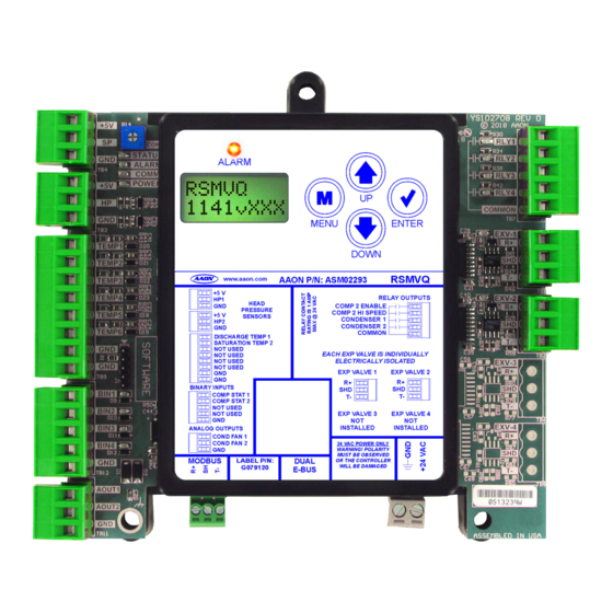
COND FAN 1 COND FAN 2 24 VAC POWER ONLY WARNING! POLARITY MUST BE OBSERVED MODBUS LABEL P/N: DUAL OR THE CONTROLLER WILL BE DAMAGED G079120 E-BUS 4.10 Note: All dimensions are in inches. Figure 1: RSMVQ Dimensions RSMVQ Technical Guide... -
Page 7: Installation And Wiring
Please carefully read and apply the following information when wiring the unit controller, RSMVQ, and any associated module. Correct wiring of the AAON unit controller and its modules is 1. All wiring is to be in accordance with local and the most important factor in the overall success of the installation national electrical codes and specifications. -
Page 8: Wiring
RSMVQ Inputs Wiring RSMVQ Wiring Condenser and Compressor Configuration Options The RSMVQ uses an E-BUS cable to connect to the VCCX2 Please see pages 31-34 for condenser and compressor Controller. Only one RSMVQ can be connected. There are two configuration details. -
Page 9: Rsmvq Outputs Wiring
24 VAC power only, Controller 1 amp maximum load. Copeland VFD Drive Board Ground shield Ground shield wire on one end wire on one end RS-485 Interface Copeland Danfoss VFD Packaged VFD Figure 3: RSMVQ Outputs Wiring RSMVQ Technical Guide... -
Page 10: Inputs And Outputs
INPUTS AND OUTPUTS RSMVQ Module Inputs/Outputs Map Inputs/Outputs Map See Table 2, this page, for the RSMVQ inputs and outputs. REFRIGERATION SYSTEM MODULE FOR VFD HEAT PUMP COMPRESSORS Analog Inputs Head Pressure Transducer 1 (HP1) Head Pressure Transducer 2 (HP2) -
Page 11: Rsmvq Inputs And Outputs
Line Temperature Sensor wired directly to the drive. Units with Danfoss VFDs will have a Discharge Line Temperature Sensor The EXV-2 is the communications port for EXV setpoints and wired to TEMP 1 of the RSMVQ. status communications. TEMP2 - Saturation Temperature Sensor 2... -
Page 12: Sequence Of Operations
Saturation Temperatures are above their respective Setpoints, the compressors will modulate up. If the Supply or Saturation 1. Staging begins when the RSMVQ Module obtains the Temperatures are below their Setpoints, the compressors will Reheat Valve position and Reheat Supply Air Error modulate down. -
Page 13: Envelope Protection
Figure 6: Copeland™ ZPV0662E Envelope Figure 4: Danfoss VZH028, VZH035, VZH044 Envelope Figure 7: Copeland™ ZPV0962E Envelope Figure 5: Danfoss VZH052 and VZH065 Envelope RSMVQ Technical Guide... -
Page 14: Electronic Expansion Valve Operation And Head Pressure Control
260 - 340 psig 100% 340 psig The RSMVQ can monitor a head pressure transducer and control a condenser fan to maintain a Head Pressure Setpoint. Table 3: Compressor Speed/Head Pressure A condenser relay is commanded on when the first compressor is enabled. -
Page 15: Lcd Screens
The MENU key cancels editing when in Edit Mode. The screen you were editing will return to its original value and the underscore will disappear. A second press of the MENU key will return you to the Main Menu. Table 5: Editing Key Functions RSMVQ Technical Guide... -
Page 16: Main Screens Map
LCD SCREENS Main Screens Map RSMVQ Main Screens Map Press to go to SETPOINT STATUS screens. Refer to the following map when navigating through the LCD Main Screens. To scroll through the screens, press the <MENU> SETPOINT button. STATUS RSMVQ Press to scroll through SETPOINT STATUS screens. -
Page 17: Module Screens
LCD SCREENS Module Screens RSMVQ Module Screens #OF COMP 1 or 2 Refer to the following map when navigating through the RSMVQ Screens. From the RSMVQ MODULE Screen, press <ENTER> to scroll through the screens. # OF COMPRESSORS RSMVQ 1141vXXX... -
Page 18: System Status Screens
COMP A2 ON/OFF or HI EXV VALVE 2 POSITION 0-100% or NOT USED SPEED/LO SPEED COMPRESSOR 2 ON, OFF, HI SPEED, or LO SPEED FIXED ON/OFF: Compressor is on or off. TWO STEP: High Speed or Low Speed RSMVQ Technical Guide... -
Page 19: Sensor Status Screens
HEAD PRESSURE 2 READING FROM INPUT CALC CT XX DEG SUPRHT 1 CALCULATED COIL TEMPERATURE (Saturated Temperature) XX DEG CURRENT SUPERHEAT 1 CALCULATION SATCOIL2 XX DEG SATURATION LINE: TEMP 2 READING FROM INPUT Only appears if configured for two compressors/circuits. RSMVQ Technical Guide... -
Page 20: Alarms Screens
RSMVQ and the five minutes if the sensor is detected. AAON controller. This can be the result of a bad cable, a missing cable, or the module not being configured properly. This alarm will occur if the coil COIL 2 TEMP 2 FAILURE: temperature is not within operable range (below -32ºF or above... -
Page 21: Alarm History Screens
MODBUS TIMEOUT: The screen will display minutes for the first 60 NOTE: between the RSMVQ and Compressor VFD. minutes of alarm occurrence, hours for the next Indicates an alarm on the Danfoss VFD. 72 hours of alarm occurrence, and days for the DANFOSS VFD: next 30 days of alarm occurrence. -
Page 22: Setpoint Status Screens
HEAD PRESSURE SETPOINT 2 Valid range is 260-475 psig. Default is 340 psig. SPRHT SP SUPERHEAT SETPOINT SETTING Valid range is 1-30ºF. Default is 15ºF. LOW SUCT 95 PSIG LOW SUCTION PRESSURE SETPOINT SETTING Default is 95 psig. RSMVQ Technical Guide... -
Page 23: Copeland™ Packaged Vfd Screens
MAX RPM CONNECT? MAXIMUM RPM Maximum speed programmed into the VFD in rpm. CONNECTION STATUS YES or NO. VFD is connected and communicating with the RSMVQ. NO ALARMS or ALARM CODE MB RETRY ALARM CODE Alarm code is read from the VFD. -
Page 24: Danfoss Vfd Screens
MAX REF CONNECT? MAXIMUM SPEED Maximum speed programmed into the VFD in RPM. CONNECTION STATUS YES or NO. VFD is connected and communicated to the RSMVQ. MIN REF MB RETRY MINIMUM SPEED NOT = 0! or CONFIRMED Minimum speed programmed into the VFD. For proper speed command this should always say confirmed meaning it is set to zero. -
Page 25: Danfoss Vfd Screens
Compressor running hours read from VFD. VFD HRS VFD RUNNING HOURS VFD running hours read from VFD. MODEL# MODEL NUMBER Compressor model number read from VFD. DRIVE# DRIVE NUMBER Type of Danfoss VFD - CDS803 or CDS303. RSMVQ Technical Guide... -
Page 26: Copeland™ Vfd Screens
CURRENT AMPS CURRENT SPEED OF COMPRESSOR Live current reading of compressor in amps. Compressor speed read from VFD in rpm. When in Force Mode, speed can be adjusted from this screen by using the <UP> and <DOWN> buttons. RSMVQ Technical Guide... -
Page 27: Copeland™ Vfd Screens And Dmq Exv Screens
DETECTED Software version read from the VFD. EXV1-4 DETECTED or NODETECT If DMQ is detected and communicating with RSMVQ (each connected DMQ will be displayed on a separate screen) DMQ1-4 PSI DMQ1-4 SUCTION PRESSURE READING Suction Pressure reading from DMQ1 through DMQ4... -
Page 28: Troubleshooting
Superheat Controller. If the LED is on solid, that indicates the expansion valve is initializing at startup. no communication to the Superheat Controller. - Every time the RSMVQ Module receives a valid E-BUS COMM - This yellow LED will blink to indicate communication... -
Page 29: Temperature Sensor Testing
NOTE: If the voltage is above 4.88 VDC, then the sensor or wiring is “open.” If the voltage is less than 0.05 VDC, then the sensor or wiring is shorted. Table 6: Temperature, Resistance, and Voltage for Type III Sensors RSMVQ Technical Guide... -
Page 30: Head Pressure Transducer
If you suspect there is a problem related to the head pressure transducer, measurements can be taken at the HP terminal. See Table 7, this page. Head Pressure Transducer Chart Voltage Pressure Voltage Pressure Table 7: Head Pressure Transducer Chart RSMVQ Technical Guide... -
Page 31: Appendix A: System Configuration
In Single Condenser Per Module wiring configuration, the Condenser Signal is wired to AO1 and the RLY3 is enabled. Refer to the figures below for Prism 2 configuration and Modular Service Tool Screen selection. RSMVQ Condenser Options Configuration Screen RSM#1 CONFIGURATION Condenser Options 1 Cond per RSMV USE <... -
Page 32: Two Condensers Per Module
Condenser Signals are wired to AO1 and AO2 and RLY3 and RLY4. Refer to the figures below for Prism 2 configuration and Modular Service Tool Screen selection. RSMVQ Condenser Options Configuration Screen RSM#1 CONFIGURATION Condenser Options 2 Cond per RSMV USE <... -
Page 33: Compressor Type Selection
RSMVQ’s LCD Compressor screen. If • Compressor 1 - Single Danfoss CDS803 VFD, it does not appear correctly, try cycling power to the RSMVQ. Compressor 2 - Two-Step • Compressor 1 - Single Danfoss CDS303 VFD, Compressor 2 - On/Off •... -
Page 34: Unit Tonnage Selection And Compressor Type Specification Table
Refer to Table 8, this page, for compressor type unit tonnage and minimum and maximum compressor speeds. RSMV-Q Tonnage Selection 0 Tons Compressor Tonnage Rating Figure 15: RSMVQ Unit Tonnage Selection COMPRESSOR TYPE SPECIFICATIONS TABLE Maximum VFD Minimum VFD Compressor Type(s) -
Page 35: Notes
NOTES RSMVQ Technical Guide... - Page 36 Monday through Friday, 7:00 AM to 5:00 PM Central Standard Time Controls Support website: www.aaon.com/controlstechsupport AAON Factory Technical Support: 918-382-6450 techsupport@aaon.com NOTE: Before calling Technical Support, please have the model and serial number of the unit available. PARTS: For replacement parts, please contact your local AAON Representative.
Need help?
Do you have a question about the RSMVQ and is the answer not in the manual?
Questions and answers