Table of Contents

Related Manuals for AAON RSM-DEV1


Summary of Contents for AAON RSM-DEV1
- Page 1 RSM-DEV1 Module Technical Guide ASM07687 Software SS1192 WARNING: The expansion valves installed and this module are a factory specified deviation. Contact Controls Tech support before attempting any user configuration or maintenance.
- Page 2 Factory Technical Support Phone: 918-382-6450 subject to change without notice. All rights reserved AAON Controls Support: 866-918-1100 AAON is a registered trademark of AAON, Inc., Tulsa, OK. ® ® It is the intent of AAON to provide accurate and current product information.
-
Page 3: Table Of Contents
TABLE OF CONTENTS OVERVIEW ..............................5 RSM-DEV1 Overview ............................. 5 INSTALLATION ............................6 Electrical and Environmental Requirements ......................6 Dimensions ................................7 Wiring ..................................8 Inputs and Outputs ..............................10 SEQUENCE OF OPERATIONS ......................12 Modes of Operation .............................. 12 Staging .................................. - Page 4 ..........................22 RSM-DEV1 LED Locations Figure 9: ............................. 33 S3C Valve Module Stepper Valve Locations Figure 10: ........................ 39 TABLES RSM-DEV1 Electrical and Environmental Requirements Table 1: ...................6 RSM-DEV1 Inputs and Outputs Table 2: ..........................10 Navigation Key Functions Table 3: ............................22...
-
Page 5: Overview
This module automatically configures condensers, EXVs, and compressors based on unit selection. The RSM-DEV1 uses an E-BUS cable to connect to the VCCX2 Controller. Up to four RSM-DEV1 Modules can be connected. There are two E-BUS expansion ports which allow connection to the VCCX2 Controller, communicating sensors, and other E-BUS modules. -
Page 6: Installation
Please carefully read and apply the following information when wiring the unit controller, RSM-DEV1, and any associated module. Correct wiring of the AAON unit controller and its modules is 1. All wiring is to be in accordance with local and the most important factor in the overall success of the installation national electrical codes and specifications. -
Page 7: Dimensions
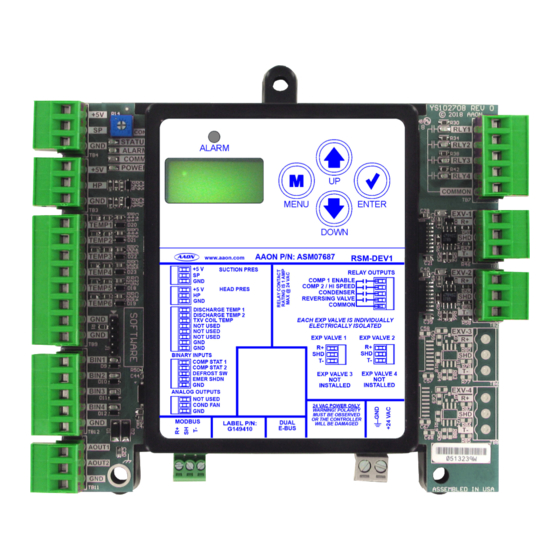
ANALOG OUTPUTS NOT USED COND FAN 24 VAC POWER ONLY WARNING! POLARITY MUST BE OBSERVED OR THE CONTROLLER MODBUS DUAL LABEL P/N: WILL BE DAMAGED E-BUS G149410 4.10 Note: All dimensions are in inches. Figure 1: RSM-DEV1 Dimensions RSM-DEV1 Technical Guide... -
Page 8: Wiring
Inputs Wiring Observe polarity! All boards must be wired with WARNING! The RSM-DEV1 uses an E-BUS cable to connect to the VCCX2 GND-to-GND and 24 VAC-to-24 VAC. Failure Controller. Up to four RSM-DEV1 Modules can be connected. Two to observe polarity will result in damage to one E-BUS expansion ports allow connection to the VCCX2 Controller, or more of the boards. -
Page 9: Figure 3: Rsm-Dev1 Outputs Wiring
GND, but only on Interface one end. Danfoss VFD NOTE: Connect jumpers from R+ to S+ and R- to S- on the drive. Drive Connect shield to GND, but only on one end. Yaskawa V1000 Figure 3: RSM-DEV1 Outputs Wiring RSM-DEV1 Technical Guide... -
Page 10: Inputs And Outputs
INSTALLATION Inputs and Outputs Inputs/Outputs Map See Table 2, this page, for the RSM-DEV1 inputs and outputs. RSM-DEV1 INPUTS AND OUTPUTS Analog Inputs Suction Pressure Transducer Head Pressure Transducer TEMP1 Discharge Line Temperature 1 TEMP2 Discharge Line Temperature 2 TEMP3... - Page 11 RLY4 - Reversing Valve Enable This relay enables the reversing valve. is generated. If Compressor 1 on module is a VFD, then compressor status is validated through VFD communications and wiring to this input is not necessary. RSM-DEV1 Technical Guide...
-
Page 12: Sequence Of Operations
Circuit 2 uses the Saturation Coil Temperature Sensor (TEMP3 input) mounted after the TXV. Compressor 2 cannot be turned off in Dehumidification NOTE: Mode unless it shuts down because of an alarm fault (see Table 9 Alarms Screens). RSM-DEV1 Technical Guide... -
Page 13: Staging
SEQUENCE OF OPERATIONS Staging Stage Types Stage Type 2 - VFD Plus On/Off The RSM-DEV1 uses different staging sequences depending on the Units affected unit configuration. Below are the different stage types the module • RNC 30 Ton can use. - Page 14 • Stage 5: VFD is on; two-step is on at high speed • Minimum run time must also be satisfied before two- step stages down. • VFD resets to recommended start speed (3,600 RPM Copeland; 3,000 RPM Danfoss). RSM-DEV1 Technical Guide...
- Page 15 • Controlling temperature is above the staging window for • Two-Step not allowed to stage off in Dehumidification cooling or below the staging window for heating. Mode • VFD resets to recommended start speed (3,600 RPM Copeland; 3,000 RPM Danfoss). RSM-DEV1 Technical Guide...
- Page 16 • A1 turns on at recommended start speed (3,600 RPM cooling or above the staging window for heating. Copeland; 3,000 RPM Danfoss). • Stage delay has been met. • For Dehumidfication Mode, A1 turns on immediately. No conditions needed. RSM-DEV1 Technical Guide...
- Page 17 • A1 minimum run time met. • Stage delay has been met. • Controlling temperature is below the staging window for cooling or above the staging window for heating. • If in Dehumidification Mode, A1 is not allowed to stage off. RSM-DEV1 Technical Guide...
- Page 18 • A1 turns on at recommended start speed (3,600 RPM • A1 and C1 at maximum speed. Copeland). • Stage delay has been met. • Controlling temperature is above the staging window for cooling or below the staging window for heating. RSM-DEV1 Technical Guide...
- Page 19 To Cool/Heat Mode • Stage 2 is not a valid cool/heat stage. If in stage 2, go directly to 3. • Stage 4 is not a valid cool/heat stage. If in stage 4, go directly to stage 5 RSM-DEV1 Technical Guide...
-
Page 20: Envelope Protection
Figures 5-8, this page, are examples of compressor envelopes. Figure 4: Danfoss VZH028, VZH035, VZH044 Envelope Figure 6: Copeland ZPV0662E Envelope Figure 5: Danfoss VZH052 and VZH065 Envelope Figure 7: Copeland ZPV0962E Envelope RSM-DEV1 Technical Guide... -
Page 21: Component Operation
Head Pressure Control The RSM-DEV1 can monitor a head pressure transducer and control a condenser fan to maintain a Head Pressure Setpoint. The condenser fan starting speed varies based on outside air temperatures. -
Page 22: Lcd Screens
The <MENU> key cancels editing when in Edit Mode. The screen you were editing will return to its original value and the underscore will disappear. A second press of the <MENU> key will return you to the Main Menu. Table 4: Editing Key Functions RSM-DEV1 Technical Guide... -
Page 23: Main Screens Map
Contact Controls Tech Support before making WARNING: any changes to the configuration of this module. COMP Z1= XXXXXXXX See the following pages for detailed descriptions of NOTE: the options for each menu. #OF COND UNIT # STAGE ID XXX XX RSM-DEV1 Technical Guide... -
Page 24: Screen Descriptions
Main Screens Module Screens Refer to the following table when navigating through the LCD Refer to the following table when navigating through the module Main Screens. screens. From the RSM-DEV1 screen, press to scroll <ENTER> through the screens. Press the button to navigate between the top level screens. -
Page 25: Table 7: System Status Screens
Condenser fan operation status. Options are: XXX% • 0-100% • NOT USED - Condenser fan not in use • OFF - Condenser is off EXV ZX Expansion valve operation status XXX% 0-100% Table 7: System Status Screens RSM-DEV1 Technical Guide... -
Page 26: Table 9: Alarms Screens
This alarm indicates that communication has been DETECTED tween the RSM and installed EXV. TIMEOUT lost between the RSM-DEV1 and the AAON control- ler. This can be the result of a bad cable, a missing cable, or the module not being configured properly. EMERGNCY... -
Page 27: Table 10: Alarm History Screens
High Head Pressure Detected BIN4 ALM BI4 is open, if configured. LOW SP Low Suction Pressure Detected MODBUS MODBUS Not Detected LOW SHX Low Superheat Detected HDLT ALM High Discharge Temperature Detected Table 10: Alarm History Screens RSM-DEV1 Technical Guide... -
Page 28: Table 11: Setpoint Status Screens
15ºF. Measured in degrees Fahrenheit. LOW SUCT Low Suction Pressure Setpoint. Default is 95 psig. XX PSIG Measured in PSIG. COILT SP Coil Temperature Setpoint. Valid range is 35-60ºF. XX.XºF Default is 40ºF.Measured in degrees Fahrenheit. Table 11: Setpoint Status Screens RSM-DEV1 Technical Guide... -
Page 29: Table 12: Yaskawa Vfd Screens
XXXAMPS Measured in amps DEMAND RPM MIN RPM MAX RPM MAX XXXX RPM XXXX RPM XXXX RPM Measured in RPM RPM MIN RPM MIN XXXX RPM Measured in RPM DEMAND Table 12: Yaskawa VFD Screens XX.X Hz RSM-DEV1 Technical Guide... -
Page 30: Table 13: Danfoss Vfd Screens
• VZH035 • VZH044 • VZH052 • VZH065 • UNKNOWN! If UNKNOWN is shown, check that proper unit is selected in Prism 2. DRIVE# Drive number. Options are: XXXXXXXX • CDS803 • CDS303. Table 13: Danfoss VFD Screens RSM-DEV1 Technical Guide... -
Page 31: Table 14: Dmq Exv Screens
DMQ screens. From the EXV TYPE DMQ Screen, press <ENTER> XXX PSIG screens shown depends on unit configuration. to scroll through the screens. Table 14: DMQ EXV Screens EXV TYPE EXV X DETECTED EXVX PSI XXX PSIG RSM-DEV1 Technical Guide... -
Page 32: Table 15: Sporlan Exv Screens
VER: XX FIRMWARE REFRIGNT The type of refrigerant being used. Options are: S3C2 V2? R410a • R410a VER: XX 5 WIRE ERROR! will show up if there is a configuration issue. Table 15: Sporlan EXV Screens REFRIGNT R410a RSM-DEV1 Technical Guide... -
Page 33: Troubleshooting
Binary Input LEDs - This green LED lights up when Compressor Status 1 input BIN1 The RSM-DEV1 is equipped with LEDs that can be used to has 24VAC present. verify operation and perform troubleshooting. There are LEDs for communication, operation modes, and diagnostic codes. See Figure... -
Page 34: Sensor Testing
NOTE: If the voltage is above 4.98 VDC, then the sensor or wiring is “open.” If the voltage is less than 0.38 VDC, then the sensor or wiring is shorted. Table 16: Temperature, Resistance, and Voltage for Discharge Sensors RSM-DEV1 Technical Guide... -
Page 35: Table 17: Discharge Thermistor Temperature And Resistance
3.00 If the voltage is above 4.98 VDC, then the sensor or wiring is “open.” If the voltage is less than 0.38 VDC, then the sensor or wiring is shorted. Table 17: Discharge Thermistor Temperature and Resistance RSM-DEV1 Technical Guide... -
Page 36: Transducer Testing
Use the voltage column to check the Suction Pressure Transducer 21.19 -6.1 80.94 while connected to the RSM-DEV1 Module. The VCCX2 and the 24.49 -4.4 87.16 RSM-DEV1 Module must be powered for this test. Read voltage 27.80... -
Page 37: Table 19: Head Pressure Transducer Chart
If you suspect there is a problem related to the head pressure transducer, measurements can be taken at the HP terminal. See Table 19, this page. HEAD PRESSURE TRANSDUCER CHART Voltage Pressure Voltage Pressure Table 19: Head Pressure Transducer Chart RSM-DEV1 Technical Guide... -
Page 38: Appendix A: Vfd Configuration
Default = 1 Enabled to fault on comm loss H5-06 Drive transmit wait time Default = 5 ms H5-07 RTS Control Selection Default = 1: Enabled – RTS Switches while sending H5-09 CE Detection Time NOT Default: Set to 10.0 seconds RSM-DEV1 Technical Guide... -
Page 39: Appendix B: S3C Valve
S3C1 V2? 5 WIRE When on the individual configuration screens, NOTE: pushing UP will select 5 WIRE and pushing DOWN will select 4 WIRE. Use ENTER to confirm your selection. Figure 10: S3C Valve Module Stepper Valve Locations RSM-DEV1 Technical Guide... - Page 40 RSM-DEV1 Technical Guide Rev. A · 231215 AAON Controls Tech Support: 866-918-1100 | 918-382-6450 | controls.support@aaon.com Monday through Friday, 7:00 AM to 5:00 PM Central Time Controls Tech Support website: www.aaon.com/aaon-controls-technical-support AAON Factory Technical Support: 918-382-6450 | techsupport@aaon.com NOTE: Before calling Technical Support, please have the model and serial number of the unit available.
Need help?
Do you have a question about the RSM-DEV1 and is the answer not in the manual?
Questions and answers