Table of Contents
Advertisement
Quick Links
Advertisement
Table of Contents

Related Manuals for AAON RSMVQ2R


Summary of Contents for AAON RSMVQ2R
- Page 1 RSMVQ2R Technical Guide...
- Page 2 ® 2425 South Yukon Ave. Copyright March 2021 AAON, Inc. Tulsa, OK 74107-2728 AAON is a registered trademark of AAON, Inc., Tulsa, OK. ® www.aaon.com Copeland Digital Scroll™ is a registered trademark of Factory Technical Support Phone: 918-382-6450 Copeland Corporation, Sidney, OH AAON ®...
-
Page 3: Table Of Contents
RSMVQ2R Inputs Wiring ............................8 RSMVQ2R Outputs Wiring ............................ 9 INPUTS AND OUTPUTS ....................10 RSMVQ2R Module Inputs/Outputs Map ......................10 RSMVQ2R Inputs and Outputs ..........................11 SEQUENCE OF OPERATIONS ..................12 Cooling Mode, Dehumidification, and Head Pressure Control ................12 Envelope Protection .............................. - Page 4 Figure 13: .................33 Update Copeland Figure 14: ..............................33 RSMVQ2R Unit Tonnage Selection Figure 15: ........................34 TABLES RSMVQ2R Controller Electrical and Environmental Requirements Table 1: ..............7 RSMVQ2R Inputs and Outputs Table 2: ..........................10 Compressor Speed / Head Pressure Table 3: ........................14...
-
Page 5: Overview
2. Single or dual DMQ EXVs. In addition, the RSMVQ2R cannot be a Heat Pump (air-to-air or water-source) and cannot have multiple RSM modules. The RSMVQ2R uses an EBC E-BUS cable to connect to the VCCX2 Controller. -
Page 6: Rsmvq2R Dimensions
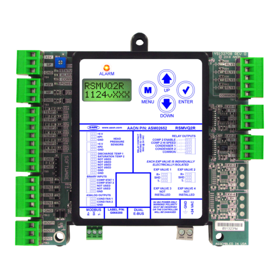
NOT USED INSTALLED INSTALLED ANALOG OUTPUTS COND FAN 1 COND FAN 2 24 VAC POWER ONLY WARNING! POLARITY MUST BE OBSERVED MODBUS LABEL P/N: DUAL OR THE CONTROLLER WILL BE DAMAGED G068350 E-BUS 4.10 Figure 1: RSMVQ2R Dimensions RSMVQ2R Technical Guide... -
Page 7: Installation And Wiring
The main unit controller and modules are national electrical codes and specifications. installed and wired at the AAON factory. Some of the following 2. All 24 VAC wiring must be connected so that all information may not apply to your installation if it was pre-wired ground wires remain common. -
Page 8: Wiring
E-BUS Modules. WARNING: Observe Polarity! All boards must be wired The RSMVQ2R uses four analog inputs, two binary inputs, four with GND-to-GND and 24 VAC-to-24 relays, and two analog outputs. See Figure 2, this page for inputs VAC. -
Page 9: Rsmvq2R Outputs Wiring
24 VAC power only. Controller 1 amp maximum load. Copeland VFD Drive Board Ground shield Ground shield wire on one end wire on one end RS-485 Interface Copeland Danfoss VFD Packaged VFD Figure 3: RSMVQ2R Outputs Wiring RSMVQ2R Technical Guide... -
Page 10: Inputs And Outputs
INPUTS AND OUTPUTS RSMVQ2R Module Inputs/Outputs Map Inputs/Outputs Map See Table 2, this page for the RSMVQ2R inputs and outputs. REFRIGERATION SYSTEM MODULE FOR VFD HEAT PUMP COMPRESSORS Analog Inputs Head Pressure Sensor 1 (HP1) Head Pressure Sensor 2 (HP2) -
Page 11: Rsmvq2R Inputs And Outputs
The Electronic Expansion Valve 2 is the communications port Danfoss VFDs will have a Discharge Line Temperature Sensor for DMQ EXV setpoints and status communications. wired to TEMP 1 of the RSMVQ2R. RLY1 - Compressor 2 Enable TEMP2 - Saturation Temperature Sensor 2 This relay turns on Compressor 2. -
Page 12: Sequence Of Operations
Compressor 1 VFD is at minimum capacity, Compressor 1 will be turned off. 4. If the supply air temperature rises above the setpoint and Compressor 1 VFD’s minimum off time has been met, Compressor 1 will be turned back on. RSMVQ2R Technical Guide... -
Page 13: Envelope Protection
Figure 6: Copeland ZPV0662E Envelope Figure 4: Danfoss VZH028, VZH035, VZH044 Envelope Figure 7: Copeland ZPV0962E Envelope Figure 5: Danfoss VZH052 and VZH065 Envelope RSMVQ2R Technical Guide... -
Page 14: Electronic Expansion Valve Operation And Head Pressure Control
EXV to maintain the configured superheat. The Table 3: Compressor Speed / Head Pressure RSMVQ2R will communicate with the DMQ controller to set the desired superheat setpoint and to retrieve operational data for display and trending purposes. -
Page 15: Lcd Screens
The MENU key cancels editing when in Edit Mode. The screen you were editing will return to its original value and the underscore will disappear. A second press of the MENU key will return you to the Main Menu. Table 5: Editing Key Functions RSMVQ2R Technical Guide... -
Page 16: Main Screens Map
LCD SCREENS Main Screens Map RSMVQ2R Main Screens Map Press to go to VFD MENU Screens. Refer to the following map when navigating through the LCD Note: There are three separate VFD menus. The one that appears is Main Screens. To scroll through the screens, press the <MENU>... -
Page 17: Module Screens
LCD SCREENS Module Screens RSMVQ2R Module Screens #OF EXVs ISO-# Refer to the following map when navigating through the RSMVQ2R Screens. From the RSMVQ2R MODULE Screen, press to scroll through the screens. <ENTER> # OF EXPANSION MODULES RSMVQ2R 1124vXXX COMP A1=... -
Page 18: System Status Screens
COMPRESSOR 2 ON, OFF, HI SPEED, or LO SPEED FIXED ON/OFF: Compressor is on or off. TWO STEP: High Speed or Low Speed CONDFAN1 CONDENSER 1 COND FAN, NOT USED, or OFF COND FAN MODULATING PERCENTAGE: 0-100% RSMVQ2R Technical Guide... -
Page 19: Sensor Status Screens
HEAD PRESSURE 2 READING FROM INPUT SATCOIL2 XX DEG SUPRHT 1 SATURATION LINE: TEMP 2 READING FROM INPUT XX DEG Only appears if configured for two compressors/circuits. CURRENT SUPERHEAT 1 CALCULATION SUPRHT 2 XX DEG CURRENT SUPERHEAT 2 CALCULATION RSMVQ2R Technical Guide... -
Page 20: Alarms Screens
EBUS SLAVE (SLV) TIMEOUT: 310ºF). This could be the result of a bad sensor or faulty wiring. communication has been lost between the RSMVQ2R and the This alarm will shut down the system. The system will reset after Main controller. This can be the result of a bad cable, a missing five minutes if the sensor is detected. -
Page 21: Alarm History Screens
UNSAFE SP —High Superheat 1 Failure HI SH1 —High Superheat 2 Failure HI SH2 —MODBUS Not Detected MODBUS —Danfoss VFD Not Detected DF VFD —High Discharge Temperature Detected HIGH DT —No Head Pressure 2 Sensor Detected HP2 SENSE RSMVQ2R Technical Guide... -
Page 22: Setpoint Status Screens
HEAD PRESSURE SETPOINT 2 Valid range is 260-475 PSI. Default is 340 PSI. SPRHT SP SUPERHEAT SETPOINT SETTING Valid range is 1-30 degrees. Default is 15 degrees. LOW SUCT 95 PSI LOW SUCTION PRESSURE SETPOINT SETTING Default is 95 PSI. RSMVQ2R Technical Guide... -
Page 23: Copeland Packaged Vfd Screens
MAX RPM CONNECT? MAXIMUM RPM Maximum speed programmed into the VFD in RPM. CONNECTION STATUS YES or NO. VFD is connected and communicated to the RSMVQ2R. NO ALARMS or ALARM CODE MB RETRY ALARM CODE Alarm code is read from the VFD. -
Page 24: Danfoss Vfd Screens
NOT = 0! or CONFIRMED CONNECTION STATUS Minimum speed programmed into the VFD. For proper speed YES or NO. VFD is connected and communicated to the RSMVQ2R. command this should always say confirmed meaning it is set to zero. MB RETRY... - Page 25 LCD SCREENS Danfoss VFD Screens MODEL# MODEL NUMBER Compressor model number read from VFD. DRIVE# DRIVE NUMBER Type of Danfoss VFD - CDS803 or CDS303. RSMVQ2R Technical Guide...
-
Page 26: Copeland Vfd Screens
CURRENT SPEED OF COMPRESSOR Live current reading of compressor in Amps. Compressor speed read from VFD in RPM. When in Force Mode, speed can be adjusted from this screen by using the UP and DOWN arrow keys. RSMVQ2R Technical Guide... -
Page 27: Copeland Vfd Screens And Dmq Exv Screens
DETECTED Software version read from the VFD. EXV1-4 DETECTED or NODETECT If DMQ is detected and communicating with RSMVQ2R (each connected DMQ will be displayed on a separate screen) DMQ1-4 PSI DMQ1-4 SUCTION PRESSURE READING Suction Pressure reading from DMQ1 through DMQ4... -
Page 28: Troubleshooting
Operation Binary Input LEDs The RSMVQ2R is equipped with LEDs that can be used to This green LED will light up when Compressor Status 1 verify operation and perform troubleshooting. There are LEDs BIN1 - contact is closed. -
Page 29: Temperature Sensor Testing
Note: If the voltage is above 4.88 VDC the sensor or wiring is “open.” If the voltage is less than 0.05 VDC, the sensor or wiring is shorted. Table 6: 0-5V Temperature Sensor - Voltage & Resistance for Type III Sensors RSMVQ2R Technical Guide... -
Page 30: Head Pressure Transducer
If you suspect there is a problem related to the head pressure transducer, measurements can be taken at the HP terminal. See Table 7, this page. Head Pressure Transducer Chart Voltage Pressure Voltage Pressure Table 7: Head Pressure Transducer Chart RSMVQ2R Technical Guide... -
Page 31: Appendix A: System Configuration
Condenser Signal is wired to AO1 and the Condenser Relay RLY3 is enabled. Refer to the figures below for Prism 2 configuration and Modular Service Tool Screen selection. RSMVQ2R Condenser Options Configuration Screen RSM#1-4 CONFIGURATION Condenser Options 1 Cond per RSMV USE <... -
Page 32: Two Condensers Per Module A
Condenser Signals are wired to AO1 and AO2 and Condenser Relays RLY3 and RLY4. Refer to the figures below for Prism 2 configuration and Modular Service Tool Screen selection. RSMVQ2R Condenser Options Configuration Screen RSM#1-4 CONFIGURATION Condenser Options 2 Cond per RSMV USE <... -
Page 33: Compressor Type Selection
Prism 2 Compressor Type Selection Copeland Compressor Model Selection Refer to Figure 13, this page in selecting Copeland Compressor Refer to Figure 12, this page in setting RSMVQ2R compressor Model selection which is located in the Miscellaneous Setpoints type selection. -
Page 34: Unit Tonnage Selection And Compressor Type Specification Table
Refer to Table 8, this page for compressor type unit tonnage and minimum and maximum compressor speeds. RSMV-Q Tonnage Selection 0 Tons Compressor Tonnage Rating Figure 15: RSMVQ2R Unit Tonnage Selection COMPRESSOR TYPE SPECIFICATIONS TABLE Maximum VFD Minimum VFD Compressor Type(s) - Page 35 NOTES RSMVQ2R Technical Guide...
- Page 36 RSMVQ2R Technical Guide G068360 · Rev. A · 210322 AAON Factory Technical Support: 918-382-6450 techsupport@aaon.com AAON Controls Support: 866-918-1100 Monday through Friday, 7:00 AM to 5:00 PM Central Standard Time Controls Support website: www.aaon.com/controlstechsupport NOTE: Before calling Technical Support, please have the model and serial number of the unit available.
Need help?
Do you have a question about the RSMVQ2R and is the answer not in the manual?
Questions and answers