
Subscribe to Our Youtube Channel
Related Manuals for FuzzDog PHASE 90


Summary of Contents for FuzzDog PHASE 90
- Page 1 PHASE 90 One knob of glorious phasey phun Contents of this document are ©2019 Pedal Parts Ltd. No reproduction permitted without the express written permission of Pedal Parts Ltd. All rights reserved.
-
Page 2: Important Notes
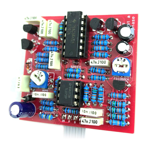
Important notes If you’re using any of our footswitch daughterboards, DOWNLOAD THE DAUGHTERBOARD DOCUMENT • Download and read the appropriate build document for the daughterboard as well as this one BEFORE you start. • DO NOT solder the supplied Current Limiting Resistor (CLR) to the main circuit board even if there is a place for it. - Page 3 Schematic + BOM 150K SPEED 500KC 470K 150K 470K FBACK 47K trim** 150K 150K BIAS 250K trim 150K * / ** see page 5 15u elec 5.1v zener 100u elec 1N4001 100n 2N5087 Q2-5 Matched FETs* TL072 TL074 150K...
- Page 5 See below. BIASING The power and signal pads on the PCB conform to the FuzzDog Direct Connection format, so can be paired with the appropriate daughterboard for Use the bias trimmer to adjust the voltage at the quick and easy offboard wiring. Check the separate gates of the FETs.
- Page 6 Test the board! Check the relevant daughterboard document for more info before you undertake this stage. UNDER NO CIRCUMSTANCES will troubleshooting help be offered if you have skipped this stage. No exceptions. Once you’ve finished the circuit it makes sense to test is before starting on the switch and LED wiring.
- Page 7 Wire it up (if using a daughterboard please refer to the relevant document) BOARD BOARD INPUT BOARD BOARD BOARD BOARD BOARD BOARD BATTERY Wiring shown above will disconnect the battery when you remove the jack plug from the input, and also when a DC plug is inserted. The Board GND connections don’t all have to directly attach to the board.
-
Page 8: Drilling Template
Wiggle room = good! This template is a rough guide only. You should ensure correct marking of your enclosure before drilling. You use this template at your own risk. Pedal Parts Ltd can accept no responsibility for incorrect drilling of enclosures. FuzzDog.co.uk...
Need help?
Do you have a question about the PHASE 90 and is the answer not in the manual?
Questions and answers