Table of Contents
Advertisement
Quick Links
This document is provided with the DRV10963 customer evaluation module (EVM) as a supplement to the
DRV10963 datasheet (SLAS955A). It details the hardware implementation of the EVM and gives a step-
by-step introduction to the device operation and tuning process using DRV10963 GUI.
1
...................................................................................................................
2
3
3.1
3.2
3.3
4
4.1
4.2
5
5.1
5.2
5.3
5.4
5.5
6
6.1
6.2
6.3
6.4
7
7.1
7.2
1
2
3
4
5
6
7
8
9
10
11
12
13
14
SLAU643 - July 2015
Submit Documentation Feedback
..............................................................................................
.....................................................................................
..........................................................................................................
.............................................................................................
...................................................................................
...........................................................................................
............................................................................................................
.............................................................................................
...........................................................................................
..................................................................................................
................................................................................................................
...........................................................................................
....................................................................................
.........................................................................................
................................................................................................................
...........................................................................................
..........................................................................................................
............................................................................................
.....................................................................................
........................................................................................
................................................................................
...................................................................................................
..............................................................................................................
.......................................................................................................
......................................................................................................
................................................................................
Copyright © 2015, Texas Instruments Incorporated
DRV10963 Evaluation Module
Contents
........................................................
...................................................................
.............................................................................
.....................................................................
List of Figures
...............................................
.................................................................
..................................................................
..............................................................................
..........................................................
..............................................................................
User's Guide
SLAU643 - July 2015
DRV10963 Evaluation Module
2
3
4
4
4
5
5
5
5
6
6
6
7
7
8
13
13
16
18
18
20
20
22
3
6
7
8
9
10
11
12
12
13
14
14
14
14
1
Advertisement
Table of Contents

Related Manuals for Texas Instruments DRV10963


Summary of Contents for Texas Instruments DRV10963
-
Page 1: Table Of Contents
SLAU643 – July 2015 DRV10963 Evaluation Module This document is provided with the DRV10963 customer evaluation module (EVM) as a supplement to the DRV10963 datasheet (SLAS955A). It details the hardware implementation of the EVM and gives a step- by-step introduction to the device operation and tuning process using DRV10963 GUI. -
Page 2: Drv10963 Evm Kit Contents
4. USB cable 5. 10-pin ribbon cable to connect USB2ANY and DRV10963 motherboard 6. DRV10963 EVM GUI The DRV10963 EVM boards and GUI are designed to work together for tuning device to optimize the performance for a given application. DRV10963 Evaluation Module SLAU643 –... -
Page 3: Introduction
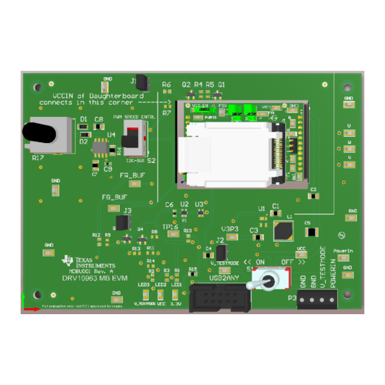
The EVM is a combination of a motherboard and daughterboard. The motherboard includes a TLC555 timer configured to supply a PWM to the DRV10963 and a potentiometer to adjust the speed of the motor by varying the duty cycle of the PWM and has USB2ANY connector to communicate with DRV10963 GUI. -
Page 4: Drv10963 Motherboard Connectors
8, 9, 10, 11 Table 2. Connector P2: Daughterboard Description VCC- 5-Volt power input 4, 5 Phase-W 6, 7 Phase-U 8, 9 Phase-V 10, 11 DRV10963 Evaluation Module SLAU643 – July 2015 Submit Documentation Feedback Copyright © 2015, Texas Instruments Incorporated... -
Page 5: Usb To Any Connector
SDATA- Data signal for I2C communication with GUI DRV10963 Daughterboard Connectors Motor Output Connector The DRV10963 daughterboard provides the 3-terminal connector P3 to connect 3-phase BLDC motor. Pin assignment of terminal P3 is as follows: Description Interface Connectors to Motherboard P1, P2 Connectors P1,P2 are used to interface signals coming from the motherboard to the device via socket. -
Page 6: Quick Start Guide
If this your first encounter with the DRV10963, before proceeding to next step, install the following software packages to use the DRV10963 GUI for tuning the motor: 1. The DRV10963 EVM is provided with a GUI to configure the device and tune the application. Refer to DRV10963_2P0 User Manual.pdf present (C:\Program Files (x86)\Texas Instruments\DRV10963_2P0 EVM\Documents) in the GUI-installed directory for instructions to download and install the GUI application. -
Page 7: Jumpers And Switch Setup Settings
C clock. Powering-Up EVM DRV10963 EVM requires two power supply sources, that is, 5 V and 6.2 V to work with the GUI to enable C interface for register configuration. Note that programmed device needs only one 5-V supply in the final end-application circuit. -
Page 8: Tuning Gui: To Configure Motor Parameter
Figure 5 appears as soon as the GUI launches. The "CONNECTED" block should turn green indicating that the GUI is successfully connected to USB2ANY. DRV10963 Evaluation Module SLAU643 – July 2015 Submit Documentation Feedback Copyright © 2015, Texas Instruments Incorporated... -
Page 9: Gui Screen With Successful I2C Interface
Figure 6. These default values correspond to the factory programmed part DRV10963JJ. Refer to the DRV10963 datasheet for a detailed explanation of different versions of DRV10963 and descriptions of tunable parameters. •... -
Page 10: Default Configuration Parameters
DRV10963JM version. In same way, load and configure other versions of DRV10963 to test the performance. To enable motor spin, open the jumper J1 on the motherboard and use POT R-17 for speed control. -
Page 11: Loading Drv10963Jm Configuration Parameter To Device
Quick Start Guide www.ti.com Figure 7. Loading DRV10963JM Configuration Parameter to Device SLAU643 – July 2015 DRV10963 Evaluation Module Submit Documentation Feedback Copyright © 2015, Texas Instruments Incorporated... -
Page 12: Drv10963Jm Configuration Parameter
8. If only one of the preloaded configurations spins the motor, then obviously that is the part number to order to control the motor. However, if two or more spin the motor, then refer to Figure Figure 9. Initial Tuning Flow Chart DRV10963 Evaluation Module SLAU643 – July 2015 Submit Documentation Feedback Copyright © 2015, Texas Instruments Incorporated... -
Page 13: Tuning Guide
Each one of the parameters that you can configure with the GUI will change how your motor reacts to the DRV10963 device. Read the description of each one of the parameters below and then choose if you would like to make the changes suggested. Be sure to connect a current probe to phase V to observe the phase current during tuning. -
Page 14: Correct Align Time And Acceleration Rate
In other words, if your desired RPM is 3000, then the open to close loop threshold should be 1/4 × (500 rpm) = 125 Hz. Therefore, the open to close loop threshold should be around 50≈125 Hz. DRV10963 Evaluation Module SLAU643 – July 2015 Submit Documentation Feedback Copyright © 2015, Texas Instruments Incorporated... -
Page 15: Current Limit Too High
6.1.3 PWM Duty Cycle Cutoff PWM duty cycle cutoff decides the minimum operating duty cycle; this can be chosen to meet minimum speed requirements. Refer to the DRV10963 datasheet for more information about the different minimum duty cycles. 6.1.4 FG Frequency Divider The FG pin provides an indication of the speed of the motor. -
Page 16: Writing To The Otp Registers
2. As a first step to program the OTP, launch the GUI and left click "Set Default Register Value", that is, step 1. Load the custom configuration as shown in Figure 18 from the stored directory on your PC. DRV10963 Evaluation Module SLAU643 – July 2015 Submit Documentation Feedback Copyright © 2015, Texas Instruments Incorporated... -
Page 17: Load Custom Configurations To Gui
J1 on motherboard. The motor will start rotating confirming that the OTP are programmed and device is ready to use. NOTE: The DRV10963 blank version is not available off-the-shelf for direct purchase, contact TI sales or distributors for further details if custom settings for production with a blank version is desired. -
Page 18: Reading The Otp Values
The optimized performance would be to make the current funnel down until it hits closed loop control. Figure 20. OTC Threshold not Optimized DRV10963 Evaluation Module SLAU643 – July 2015 Submit Documentation Feedback Copyright © 2015, Texas Instruments Incorporated... -
Page 19: Register Error Message
Click continue and try again to "Set Default Register Values". It should work the second time, if all of the connections are correct from the Quick Start Guide in Section 5. If not, just power cycle the EVM and restart the GUI. SLAU643 – July 2015 DRV10963 Evaluation Module Submit Documentation Feedback Copyright © 2015, Texas Instruments Incorporated... -
Page 20: Schematic And Bill Of Materials
Schematic and Bill of Materials This section contains the DRV10983 schematic and bill of materials (BOM). Schematic Figure 22 shows the DRV10963 motherboard schematic. Speed Control Section Interface Connectors for Daughter Board 555 Timer as PWM Generator ~25kHz USB to Any Connector 10.0k... -
Page 21: Drv10963 Daughterboard Schematic
Schematic and Bill of Materials www.ti.com Figure 23 shows the DRV10963 daughterboard schematic. Interface connectors for Mother-Board FR select FGS select PWMIN TOSC DRV10963 device with Socket 100k PWMIN PWMIN VCC_IN TOSC TOSC To Motor Phases PWMIN 10µF 2.2µF Test Points... -
Page 22: Bill Of Materials (Bom)
Schematic and Bill of Materials www.ti.com Bill of Materials (BOM) Table 5 lists the DRV10963 motherboard bill of materials. Table 5. DRV10963 Motherboard Bill of Materials Item # Designator Value PartNumber Manufacturer Description PackageReference !PCB MDBU001 Printed Circuit Board 4.7uF... -
Page 23: Drv10963 Daughterboard Bill Of Materials
Schematic and Bill of Materials www.ti.com Table 5. DRV10963 Motherboard Bill of Materials (continued) Item # Designator Value PartNumber Manufacturer Description PackageReference SH-J1, SH-J2, SH- SPC02SYAN Sullins Connector Solutions Shunt, 100mil, Flash Gold, Black Closed Top 100mil Shunt TPS62203DBVR Texas Instruments... - Page 24 STANDARD TERMS AND CONDITIONS FOR EVALUATION MODULES Delivery: TI delivers TI evaluation boards, kits, or modules, including any accompanying demonstration software, components, or documentation (collectively, an “EVM” or “EVMs”) to the User (“User”) in accordance with the terms and conditions set forth herein. Acceptance of the EVM is expressly subject to the following terms and conditions.
- Page 25 FCC Interference Statement for Class B EVM devices NOTE: This equipment has been tested and found to comply with the limits for a Class B digital device, pursuant to part 15 of the FCC Rules. These limits are designed to provide reasonable protection against harmful interference in a residential installation.
- Page 26 【無線電波を送信する製品の開発キットをお使いになる際の注意事項】 開発キットの中には技術基準適合証明を受けて いないものがあります。 技術適合証明を受けていないもののご使用に際しては、電波法遵守のため、以下のいずれかの 措置を取っていただく必要がありますのでご注意ください。 1. 電波法施行規則第6条第1項第1号に基づく平成18年3月28日総務省告示第173号で定められた電波暗室等の試験設備でご使用 いただく。 2. 実験局の免許を取得後ご使用いただく。 3. 技術基準適合証明を取得後ご使用いただく。 なお、本製品は、上記の「ご使用にあたっての注意」を譲渡先、移転先に通知しない限り、譲渡、移転できないものとします。 上記を遵守頂けない場合は、電波法の罰則が適用される可能性があることをご留意ください。 日本テキサス・イ ンスツルメンツ株式会社 東京都新宿区西新宿6丁目24番1号 西新宿三井ビル 3.3.3 Notice for EVMs for Power Line Communication: Please see http://www.tij.co.jp/lsds/ti_ja/general/eStore/notice_02.page 電力線搬送波通信についての開発キットをお使いになる際の注意事項については、次のところをご覧くださ い。http://www.tij.co.jp/lsds/ti_ja/general/eStore/notice_02.page SPACER EVM Use Restrictions and Warnings: 4.1 EVMS ARE NOT FOR USE IN FUNCTIONAL SAFETY AND/OR SAFETY CRITICAL EVALUATIONS, INCLUDING BUT NOT LIMITED TO EVALUATIONS OF LIFE SUPPORT APPLICATIONS.
- Page 27 Notwithstanding the foregoing, any judgment may be enforced in any United States or foreign court, and TI may seek injunctive relief in any United States or foreign court. Mailing Address: Texas Instruments, Post Office Box 655303, Dallas, Texas 75265 Copyright © 2015, Texas Instruments Incorporated...
- Page 28 IMPORTANT NOTICE Texas Instruments Incorporated and its subsidiaries (TI) reserve the right to make corrections, enhancements, improvements and other changes to its semiconductor products and services per JESD46, latest issue, and to discontinue any product or service per JESD48, latest issue.
- Page 29 Mouser Electronics Authorized Distributor Click to View Pricing, Inventory, Delivery & Lifecycle Information: Texas Instruments DRV10963AEVM...
Need help?
Do you have a question about the DRV10963 and is the answer not in the manual?
Questions and answers