Advertisement
Quick Links
Advertisement

Related Manuals for TELETRAC NAVMAN Qtanium200


Summary of Contents for TELETRAC NAVMAN Qtanium200
- Page 1 Qtanium200 Installation guide 10/03/2016 V.1.2 www.TeletracNavman.com...
-
Page 2: Table Of Contents
Table of Contents • Qtanium200 Introduction • Qtanium200 wiring Trailer installation • Qtanium200 wiring Vehicle/Equipment installation • Equipment overview • Trailer Installation • Vehicle Installation • Equipment Installation • LEDs for confirmation • Verification/Support... -
Page 3: Qtanium200 Introduction
Qtanium200 Introduction The Qtanium 200 is a weatherproof Automatic Vehicle Location (AVL) unit that is designed for reliable long-term asset tracking applications that are normally tethered to 12 or 24 volt systems but may be disconnected for periods of time. It communicates with a server and allows information about the asset to be stored and monitored. -
Page 4: Qtanium200 Wiring Trailer Installation
Qtanium200 wiring – Trailer installation The Qtanium200 when installed as a standard trailer tracking product only needs connections for power and ground. Wire Color Function Description +12/24V Connect to the positive post on the asset’s battery or another suitable permanent power supply source. This connection must be fused (3 Amp). -
Page 5: Qtanium200 Wiring Vehicle/Equipment Installation
Qtanium200 wiring – Vehicle/Equipment installation The Qtanium200 when installed in a vehicle or piece of equipment will be connected using standard power, ground, and ignition connections. Wire Color Function Description +12/24V Connect to the positive post on the asset’s battery or another suitable permanent power supply source. - Page 6 Recommended Tools and Supplies Mobile electronics installation requires a variety of different tools. The following list provides a good example of the range of tools that will be required for installation. Tool List (recommendations): • Panel Popper (Snap On, Mac, Craftsman, Klein) •...
-
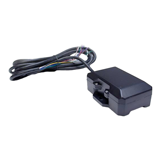
Page 7: Equipment Overview
Equipment overview The Qtanium200 consists of the device itself and an installation kit. The GPS and cellular antenna are internal on the Qtanium200 to aid in simplifying the installation process. -
Page 8: Trailer Installation
TRAILER INSTALLATION... - Page 9 Pre-Installation – Trailer installation Pre- ‐ i nstallat i on Requirements: As you are installing the Qtanium200 it is a requirement to wake the device from the hibernation mode it has been placed in for shipping. Using a drill battery or other temporary power source of between 9v-30v that you can confirm positive and negative connections –...
- Page 10 Qtanium200 device i.e. you don’t want to mount the unit directly above an axle which would block the ability for GPS reflective bounce. The Qtanium200 should be mounted with the wiring facing down, or with a “drip loop”, this is to prevent any pooling of water at the location the wiring goes into the enclosure.
- Page 11 Qtanium200 can be mounted higher on the trailer if this location is requested by the customer, this location isn’t the primary location and should only be used if the customer requests it or the Qtanium200 will not work in a lower location. Wire routing...
- Page 12 An alternate location for mounting would be the face near the 7-way connector, or on the side on a flat-bed style trailer. It is still important that wiring faces down on this installation location. On larger trailers the Qtanium200 can be mounted higher on the trailer if this location is requested by the customer.
- Page 13 Power connections Power connections are made at either the 7-way power connector between the trailer and truck or if equipped can be made at the trailers power distribution located in the rear of the trailer between the axles. Not all trailers will have the power distribution but if available can be utilized.
- Page 14 Power connections continued If the other locations listed are not accessible or not recommended for other reasons power connections can be made to the trailer harness under the trailer. Care must be taken that this connection location will not cause any issues with ongoing trailer maintenance. When making these connections you are required to use poke-and-wrap is water-proof shrinkable connectors,...
- Page 15 Power connections 7-way trailer connector If making power connections at the 7-way trailer connector you will need to gain access to the rear wires. There are many different types of 7-way connector the pictures provided are just one example. You will take both the Red and the White wires connect them together to the same power source.
- Page 16 Rear power distribution block location The power distribution block is locate in the rear of the trailer between the axles. Not all trailers will have this distribution but if they do it is recommended that power connections are made there. Look under trailer near location circled below to see if the trailer has this distribution block.
- Page 17 Power connections rear distribution block You will need to gain access to run the Qtanium200 wiring into the power distribution. You should always use the provided waterproof connectors already on the distribution block. You will simply loosen one of the connectors and run the Qtanium wires through with the factory wires, and reattach the connector.
-
Page 18: Vehicle Installation
VEHICLE INSTALLATION... - Page 19 Administration Administration – You need to document as much information as possible. The full 17 digit VIN is required on all Teletrac Navman installations, also you need to document the Make, Model, Year, and Asset number of the vehicle.
- Page 20 There may be extreme difficulties accessing the ignition switch wires, the wires may be low amperage control wires not acceptable to power the Qtanium200. In these cases the installers experience and knowledge will allow connections in other appropriate locations.)
- Page 21 The correct wire will have power when the key is in the on/run position and also while the engine is cranking. It will not have power with the key off or removed. The pink wire from the Qtanium200 will be connected here.
- Page 22 Twist Strip insulation from the source wire. Also strip approximately 1” of insulation from the fused Qtanium200 wire. Divide – Using a tool with a point divide the source wires down the middle. Poke – Insert the fused wires stripped portion through the middle.
- Page 23 In these cases, run the lead to the battery and connect it to the negative side. We recommend not using the existing factory wires attached to ground; this could cause interference or noise. It is noted that the Qtanium200 performance will be seriously degraded.
- Page 24 Qtanium200 mounting location • All equipment and wiring must be installed in a manner that will conceal its location. • It is always best to mount the unit to a flat surface; it should not be mounted on curves, dips or humps since this can degrade the security of the unit.
- Page 25 Qtanium200 mounting location The Qtanium200 must be securely mounted with a clear view of the sky.
- Page 26 Any location that blocks the internal antenna from getting a clear view of the sky • The Qtanium200 is a waterproof, dustproof, shock resistant device. As such it can be mounted in almost any location the customer would request. Inside the cab of a vehicle would be the standard location but can be moved...
- Page 27 ConEx Sensor Monitoring The Qtanium200 has two ConEx input connections, and two outputs. These are used to monitor PTO, seat belt, etc. these are able to monitor any 12/24 volt positive or negative sensor as required. Wire Color Function Description...
- Page 28 Optional: ConEx Sensor Monitoring continued Digital Inputs Digital inputs can be connected to circuits that have an “ON” and “OFF” positions. Digital inputs can be configured to be either Positive or Negative trigger . Circuit details must be noted for the correct configuration to be sent to the Qtanium thru DIRECTOR. Positive Trigger Circuits Locate and connect directly to the trigger wire.
- Page 29 Optional: ConEx Sensor Monitoring continued Digital Output ConEx Digital Out 1&2 can be configured as an output thru DIRECTOR. This output will pull low with a maximum current of 250mA when activated. Relay is required for most applications. It has an over current tripped protection.
-
Page 30: Equipment Installation
EQUIPMENT INSTALLATION... - Page 31 Administration Administration – You need to document as much information as possible. The VIN is required on all Teletrac Navman installations, also you need to document the Make, Model, Year, and Asset number of the piece of equipment.
- Page 32 Ground (black) Chassis Ground Alternator • Connect Qtanium200 red wire to the (+) battery post or (+) post on the alternator . • Insert inline weatherproof fuse-holder with a 3A fuse on the power wire. • Connect the black wire to vehicle’s chassis.
- Page 33 Ignition connection - Engine run signal R-terminal at the Alternator Figure 1 • R-terminal at the alternator or the hour meter will be ideal place to make this connection. If the R- terminal is not available/accessible, engine oil pressure switch or fuel pump circuit can be used, also. •...
- Page 34 ConEx Sensor Monitoring The Qtanium200 has two ConEx input connections, and two outputs. These are used to monitor PTO, seat belt, etc. these are able to monitor any 12/24 volt positive or negative sensor as required. Wire Color Function Description...
- Page 35 Optional: ConEx Sensor Monitoring continued Digital Inputs Digital inputs can be connected to circuits that have an “ON” and “OFF” positions. Digital inputs can be configured to be either Positive or Negative trigger . Circuit details must be noted for the correct configuration to be sent to the Qtanium thru DIRECTOR. Positive Trigger Circuits Locate and connect directly to the trigger wire.
- Page 36 Optional: ConEx Sensor Monitoring continued Digital Output ConEx Digital Out 1&2 can be configured as an output thru DIRECTOR. This output will pull low with a maximum current of 250mA when activated. Relay is required for most applications. It has an over current tripped protection.
- Page 37 Mounting the Qtanium200 Inspect the equipment to determine best possible location to mount the Qtanium. Mount away from any moving parts or linkages and away from any high heat sources. It is recommended to mounted to an interior wall of the asset and near power source, mounting location must provide clear unobstructed view of the sky.
- Page 38 VERIFICATION...
- Page 39 Verification • Verify vehicle is outside and has clear view of sky for the Live Test. • Access RIMU auto verification system using your smartphone or other smart device at https://onlineavl2sup-us.navmanwireless.com/AVL3WebSysadmin. • If you do not have a username and password please contact Navman Wireless Support at us.dispatch@navmanwireless.com or 877-778-2478 for verification.
- Page 40 LED light confirmation You are able to confirm functionality through the LEDs on the face of the Qtanium200. you are required to call into support for final installation verification but this can assist in confirming correct connections before calling. LED #1/Orange – Communications LED COMM LED –...
- Page 41 Technical support Technical Support Department Hours: Monday – Friday 7am – 7pm (Central Time) e-mail: us.support@navmanwireless.com Toll Free Phone # 877.778.2478 Local Phone # 847.832.6950...
Need help?
Do you have a question about the Qtanium200 and is the answer not in the manual?
Questions and answers