Table of Contents
Advertisement
Advertisement
Table of Contents
Troubleshooting

Subscribe to Our Youtube Channel
Related Manuals for TELETRAC NAVMAN TM470 Series


Summary of Contents for TELETRAC NAVMAN TM470 Series
- Page 1 TM470 Installation overview 6.2.2016 www.TeletracNavman.com...
- Page 2 Table of Contents • Recommended Installation Practices • Recommended Tools and Supplies • TM470 Platform overview • TM470V6 Installation overview • TM470V8 Installation overview • TM470V8 HOS Installation overview • Installation worksheet and Verification • Installation Support PRESENTATION NOTE, IF NECESSARY...
-
Page 3: Recommended Installation Practices
Recommended Installation Practices Review this installation manual to become familiar with all installation procedures and electrical wiring requirements prior to starting the installation. This installation guide has been prepared to provide you with details necessary to complete the TM470 installation. Use of proper tools and testing equipment is required. - Page 4 Recommended Tools and Supplies Mobile electronics installation requires a variety of different tools. The following list provides a good example of the range of tools that will be required for installation. Tool List (recommendations): • Panel Popper (Snap On, Mac, Craftsman, Klein) •...
- Page 5 TM470 Platform Overview Overview The purpose of this document is to provide the installer with instructions on how to install the TM470 platform in its various configurations. The installation of the system into the vehicle correctly is important for the continued reliability of the system as well as the customers satisfaction. Correctly following the installation guidelines provided and proper testing of the system and all its features are imperative.
- Page 6 TM470V6...
- Page 7 TM470V6 Installation Overview Overview This will provide the installer with instructions on how to install the TM470V6. The install of the TM470V6 is a basic 3 wire configuration with connections for ignition, power and ground. TM470V6 Kit Components • TM470 •...
- Page 8 Pre-Installation Vehicle Inspection A complete inspection of the vehicle and its major components that could be effected by the installation on the GPS system should be inspected and documented. This should be done for the benefit of the customer as well as the installer. Failure to complete and document a vehicle inspection opens the installer up to damage claims that may not be related to the installation they have performed.
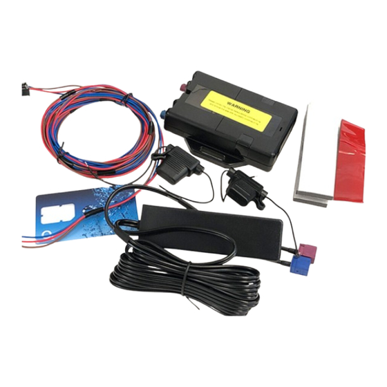
- Page 9 TM470V6 component Overview • GPS/GPRS combo antenna • Installation hardware kit • TM470 VLU • V6 Power harness...
- Page 10 TM470V6 VLU placement • All equipment and wiring must be installed in a manner that will conceal its location. • Installation must be in a dry location with minimal exposure to dust ,moisture ,heat and unnecessary vibration. • It is always best to mount the unit to a flat surface; it should not be mounted on curves, dips or humps since this can degrade the security of the unit.
- Page 11 TM470V6 VLU Placement Unapproved Locations Unapproved mounting locations: • In a Truck bed • In the Engine Compartment • Exterior of the vehicle • Any place with extreme heat such as exhaust systems or heater cores • Away from any sources of RFI such as the vehicle computer and alarm •...
-
Page 12: Power Connections
Power Connections • All connections must be either soldered (preferred) or poke and wrapped. Scotch-Loc, or T-Tap connections may not be used, if they are discovered during a QC inspection they will be corrected and installer will be billed for repairs. •... - Page 13 Power Connections continued Constant power connection • The correct wire will have power regardless of key position. This connection should have power even if the key is removed from the ignition. The red wire from the TM470 will be connected here. Ignition power connection •...
- Page 14 Poke & Wrap power connection method The recommended method of connecting the wires is by soldering. As an alternative the connection can be made using the Poke & Wrap method. This is only appropriate when the connection is made inside the cab or an area that is completely weatherproof.
-
Page 15: Ground Connection
Ground Connection Locate a strong spot in the metal near the transceiver to connect the ground lead. A good mechanical connection of the ground lead is vital, since a bad connection may cause the transceiver to locate poorly and behave erratically. Scrape away any paint or coating on the metal where the ground will be attached, and then use a star washer between the metal and the ground terminal. -
Page 16: Antenna Mounting
Antenna Mounting The TM470 antenna is a dual antenna. The GPS antenna module and the GPRS Quad Band antenna are fitted inside the single wedge type enclosure. Antenna can be mounted either covertly or exposed. While the covert installation is recommended always verify with the POC this is what the want. -
Page 17: Input/Output Connections
Input/output Connections The TM470V6 has 2 inputs and 2 outputs for connection to the vehicle. Connections are only made if required in your work order. Installer should make connection using the input wire best associated with the function they are adding. If you are making a positive PTO connection the Orange wire would be utilized, a negative would use the Grey wire. - Page 18 TM470V8...
- Page 19 TM470V8 installation Overview Overview This will provide the installer with instructions on how to install the TM470V8. The install of the TM470V8 is a basic 3 wire configuration with connections for ignition, power and ground. This unit also adds Vehicle diagnostics capture. TM470V8 Kit Components •...
- Page 20 Pre-Installation Vehicle Inspection A complete inspection of the vehicle and its major components that could be effected by the installation on the GPS system should be inspected and documented. This should be done for the benefit of the customer as well as the installer. Failure to complete and document a vehicle inspection opens the installer up to damage claims that may not be related to the installation they have performed.
- Page 21 TM470V8 component Overview • GPS/GPRS combo antenna • Installation hardware kit • TM470 VLU • V8 Power harness • Vehicle diagnostics cable – JBus extension harness will be shipped if required. • 6-pin • 9-pin • OBDII • 2013+ Mack •...
- Page 22 TM470V8 VLU placement • All equipment and wiring must be installed in a manner that will conceal its location. • Installation must be in a dry location with minimal exposure to dust, moisture, heat and unnecessary vibration. • It is always best to mount the unit to a flat surface; it should not be mounted on curves, dips or humps since this can degrade the security of the unit.
- Page 23 TM470V8 VLU Placement Unapproved Locations Unapproved mounting locations: • In a Truck bed • In the Engine Compartment • Exterior of the vehicle • Any place with extreme heat such as exhaust systems or heater cores • Away from any sources of RFI such as the vehicle computer and alarm •...
- Page 24 Power Connections JBus vehicles The system is designed to receive power and ground via the JBUS connector. Only the Ignition wire is to be connected to a source of power. Attach one end of fuse holder to the Ignition run source that will rest at ground while ignition is off (verify with suitable Multi-meter). Recommended locations are behind the ignition cylinder or behind fuse box.
- Page 25 Power Connections JBus vehicles continued Some vehicles the JBus connector does not supply the required constant and ground needed for the TM470. In these cases the installer will be required to make an alternate power connections. • All connections must either be soldered (preferred) or poke and wrapped. Scotch-Loc, or T-Tap connections may not be used, if they are discovered during a QC inspection they will be corrected and installer will be billed for repairs.
- Page 26 Power Connections JBus vehicles Alternate Power Input It is always a good practice to verify that you are getting a good constant and ground connection through the JBus connector. There are numerous situations where there will not be power or ground provided from the connector. In these situations an alternate power input is required to be sourced.
- Page 27 2013+ Mack Power and diagnostics connections Power and diagnostics connections for the 2013+ Mack is made using the special harness. After you have connected the harness into the Mack truck you will connect to the TM470 VLU using the DB15 connection. You will be required to connect the white ignition wire separately as it does not run through the DB15 connector.
- Page 28 2013+ Volvo Power and Diagnostics connections Power and diagnostics connections for the 2013+ Volvo is made using the special harness. After you have connected the harness into the Volvo truck you will connect to the TM470 VLU using the DB15 connection. You will be required to connect the white ignition wire separately as it does not run through the DB15 connector.
- Page 29 Power Connections OBDII • All connections MUST be soldered (preferred) or poke and wrapped. Scotch-Loc, or T-Tap connections may not be used, if they are discovered during a QC inspection they will be corrected and installer will be billed for repairs. •...
- Page 30 Power Connections OBDII Correct connection for constant, ignition and ground for OBDII • The installer is required to change the connection method when installing the TM470V8 into an OBDII vehicle. It is important that this is followed correctly or the customer will experience issues with the installation, specifically battery life of the vehicle. •...
- Page 31 Power Connections continued Constant power connection • The correct wire will have power regardless of key position. This connection should have power even if the key is removed from the ignition. The red wire from the TM470 will be connected here. Ignition power connection •...
- Page 32 Poke & Wrap power connection method The recommended method of connecting the wires is by soldering. As an alternative the connection can be made using the Poke & Wrap method. This is only appropriate when the connection is made inside the cab or an area that is completely weatherproof.
-
Page 33: Ground Connection
Ground Connection Locate a strong spot in the metal near the transceiver to connect the ground lead. A good mechanical connection of the ground lead is vital, since a bad connection may cause the transceiver to locate poorly and behave erratically. Scrape away any paint or coating on the metal where the ground will be attached, and then use a star washer between the metal and the ground terminal. -
Page 34: Antenna Mounting
Antenna Mounting The TM470 antenna is a dual antenna. The GPS antenna module and the GPRS Quad Band antenna are fitted inside the single wedge type enclosure. Antenna can be mounted either covertly or exposed. While the covert installation is recommended always verify with the POC this is what the want. -
Page 35: Input/Output Connections
Input/output Connections The TM470V8 has 2 inputs and 1 output for connection to the vehicle. Connections are only made if required in your work order. Installer should make connection using the input wire best associated with the function they are adding. If you are making a positive PTO connection the Orange wire would be utilized, a negative would use the Grey wire. - Page 36 TM470V8 HOS...
- Page 37 TM470V8 HOS installation Overview Overview This will provide the installer with instructions on how to install the TM470V8. The install of the TM470V8 is a basic 3 wire configuration with connections for ignition, power and ground. This unit also adds Vehicle diagnostics capture. TM470V8 Kit Components •...
- Page 38 Pre-Installation Vehicle Inspection A complete inspection of the vehicle and its major components that could be effected by the installation on the GPS system should be inspected and documented. This should be done for the benefit of the customer as well as the installer. Failure to complete and document a vehicle inspection opens the installer up to damage claims that may not be related to the installation they have performed.
- Page 39 TM470V8 HOS component Overview • GPS/GPRS combo antenna • Installation hardware kit • TM470 VLU • FIL Light • V8 Power harness • Vehicle diagnostics cable – JBus extension harness will be shipped if required. • 6-pin • 9-pin • OBDII •...
- Page 40 TM470V8 VLU placement • All equipment and wiring must be installed in a manner that will conceal its location. • Installation must be in a dry location with minimal exposure to dust, moisture, heat and unnecessary vibration. • It is always best to mount the unit to a flat surface; it should not be mounted on curves, dips or humps since this can degrade the security of the unit.
- Page 41 TM470V8 VLU Placement Unapproved Locations Unapproved mounting locations: • In a Truck bed • In the Engine Compartment • Exterior of the vehicle • Any place with extreme heat such as exhaust systems or heater cores • Away from any sources of RFI such as the vehicle computer and alarm •...
- Page 42 Power Connections JBus vehicles The system is designed to receive power and ground via the JBUS connector. Only the Ignition wire is to be connected to a source of power. Attach one end of fuse holder to the Ignition run source that will rest at ground while ignition is off (verify with suitable Multi-meter). Recommended locations are behind the ignition cylinder or behind fuse box.
- Page 43 Power Connections JBus vehicles continued Some vehicles the JBus connector does not supply the required constant and ground needed for the TM470. In these cases the installer will be required to make an alternate power connections. • All connections MUST be soldered (preferred) or poke and wrapped. Scotch-Loc, or T-Tap connections may not be used, if they are discovered during a QC inspection they will be corrected and installer will be billed for repairs.
- Page 44 Power Connections JBus vehicles Alternate Power Input It is always a good practice to verify that you are getting a good constant and ground connection through the JBus connector. There are numerous situations where there will not be power or ground provided from the connector. In these situations an alternate power input is required to be sourced.
- Page 45 2013+ Mack Power and diagnostics connections Power and diagnostics connections for the 2013+ Mack is made using the special harness. After you have connected the harness into the Mack truck you will connect to the TM470 VLU using the DB15 connection. You will be required to connect the white ignition wire separately as it does not run through the DB15 connector.
- Page 46 2013+ Volvo Power and Diagnostics connections Power and diagnostics connections for the 2013+ Volvo is made using the special harness. After you have connected the harness into the Volvo truck you will connect to the TM470 VLU using the DB15 connection. You will be required to connect the white ignition wire separately as it does not run through the DB15 connector.
- Page 47 Power Connections OBDII • All connections MUST be soldered (preferred) or poke and wrapped. Scotch-Loc, or T-Tap connections may not be used, if they are discovered during a QC inspection they will be corrected and installer will be billed for repairs. •...
- Page 48 Power Connections OBDII Correct connection for constant, ignition and ground for OBDII • The installer is required to change the connection method when installing the TM470V8 into an OBDII vehicle. It is important that this is followed correctly or the customer will experience issues with the installation, specifically battery life of the vehicle. •...
- Page 49 Power Connections continued Constant power connection • The correct wire will have power regardless of key position. This connection should have power even if the key is removed from the ignition. The red wire from the TM470 will be connected here. Ignition power connection •...
- Page 50 Poke & Wrap power connection method The recommended method of connecting the wires is by soldering. As an alternative the connection can be made using the Poke & Wrap method. This is only appropriate when the connection is made inside the cab or an area that is completely weatherproof.
- Page 51 Ground Connection Locate a strong spot in the metal near the transceiver to connect the ground lead. A good mechanical connection of the ground lead is vital, since a bad connection may cause the transceiver to locate poorly and behave erratically. Scrape away any paint or coating on the metal where the ground will be attached, and then use a star washer between the metal and the ground terminal.
- Page 52 Antenna Mounting The TM470 antenna is a dual antenna. The GPS antenna module and the GPRS Quad Band antenna are fitted inside the single wedge type enclosure. Antenna can be mounted either covertly or exposed. While the covert installation is recommended always verify with the POC this is what the want.
- Page 53 FIL Light Installation The FIL light will be mounted in the dash panel near the Garmin or CTO driver interface screen. Installer should always get mounting location approved by customer POC before drilling the dash. FIL Light is mounted after drilling an 11/32 hole in dash, care must be taken to prevent drilling into any wiring or other components...
- Page 54 Assembling the Garmin Ram Mount 1. Connect the Garmin power cable to the DB9 of the TM470. 2. Take the magnetic holder and snap it onto the top of stand mounting ball. 3. Plug the Garmin power cable into the side of the magnetic holder. Do not attempt to plug the power cable directly into the Garmin display as they are not compatible.
- Page 55 Considerations for Garmin Mounting Location • Always review the installation location of the display with the onsite customer contact, have agreed position signed off. • Ensure mounting location does not obstruct the view of the road, mirrors or warning indicators. •...
- Page 56 Garmin – TM470 Pairing Once you have assembled and connected the Garmin to the TM470 you will need to reboot the TM470 twice before the Garmin will connect. Power up the TM470 (give it about 1 minute) and connect the power cable into the back of Garmin, when the Garmin tries to connect it will time out and give you the click here to connect screen.
- Page 57 The following are examples of the Garmin mounted in full size trucks. These locations are not the only locations that the Garmin could be mounted but are locations recommended by Teletrac Navman. Always get customer POC approval on mounting location.
- Page 58 Input/output Connections The TM470V8 has 2 inputs and 1 output for connection to the vehicle. Connections are only made if required in your work order. Installer should make connection using the input wire best associated with the function they are adding. If you are making a positive PTO connection the Orange wire would be utilized, a negative would use the Grey wire.
-
Page 59: Troubleshooting
TROUBLESHOOTING... - Page 60 Troubleshooting using attached display To Access Diagnostics on Tablet press the Apps Icon then diagnostics GPRS - This function shows you if you unit is Registered on the GPRS Network. It will display the MIN: 0C00CE0A00, VIP: 12.0.206.10, RSSI: -67 AT&T Registered Notes: The MIN is the VIP# in Hex The VIP: is the Virtual IP address of the sim card it should match the VIP on the sticker of the unit...
- Page 61 Troubleshooting using attached display continued IO - This button show you if the unit is receiving ignition & input signals along with sleep entry time. It will display the following: PM:ENTRY DLY 00h00m00s OP1: ON FIL: OK IGN:ON* IN1:OFF IN2:OFF IN3:OFF IN4:OFF MDT:OFF SHOCK:OFF Notes: The PM: Entry: this number should count up after you cut the ignition off.
-
Page 62: Troubleshooting Using Leds
Troubleshooting using LEDs If for some reason you are unable to reach verifications at the completion of the installation you can quickly verify basic functionality by observing the TM470 VLU LED lights. This is not a viable alternative to speaking with verifications especially when installing VD or HOS products but can help to identify obvious issues related to the TM470 installation before calling. - Page 63 VLU Troubleshooting No Power or Ignition to the Unit - Display is Not Working: No power to Tablet no red light, Tablet stuck Check the TM470 Power & Ignition fuses. Replace if needed. (Always replace fuses with the same on loading stage amperage fuse.) Remove the Tablet and check for broken or stuck cradle Pins...
- Page 64 Installation worksheet and Verification Prior to calling Teletrac Navman make sure you have the following fields filled out. Work Order Number________ Case Number________ Date____________ Customer Name __________________________________ Installed By (tech name) _____________ Installation Company________________ Vehicle Number_______ VIN Number_________________ Odometer______ Year__ Make & Model ____________________License Plate_____________ Options Installed (JBUS, OBDII, PTO, Display, etc.) ________________...
-
Page 65: Installation Support
Installation Support Installation support can be obtained from your Field Service Manager – Western US – Shelton Simmons – 713.359.8723 Eastern US – Nahmon Sinclair (Jr) – 714.587.7263...
Need help?
Do you have a question about the TM470 Series and is the answer not in the manual?
Questions and answers