Table of Contents
Advertisement
Advertisement
Table of Contents

Related Manuals for TELETRAC NAVMAN Qube300


Summary of Contents for TELETRAC NAVMAN Qube300
- Page 1 Installation Training and Troubleshooting Qube300 M-Nav800 7/26/2016...
-
Page 2: Table Of Contents
Contents Fleet Tracking & Management Recommended Installation Practices Recommended Tools and Supplies Qube300 Hardware Identifying Correct Wires “Poke & Wrap” Solder-less Connections Chassis Ground Connection Mounting the Antenna Mobile Data Terminal: M-Nav800 ConEx Sensor Monitoring Qube Power Up Procedure Verification... -
Page 3: Fleet Tracking & Management
Fleet Tracking and Management Global Positioning Mobile iAVL Director System Satellites Cellular Network (SMS) Qube4 – ATT Qube Fleet Navman Wireless Operations Center Qtanium Fleet... -
Page 4: Recommended Installation Practices
Recommended Installation Practices Review this installation manual to become familiar with all installation procedures and electrical wiring requirements prior to starting the installation. This installation guide has been prepared to provide you with details necessary to complete the Qube installation. Use of proper tools and testing equipment is required. -
Page 5: Recommended Tools And Supplies
Recommended Tools and Supplies Basic Tools: Basic Supplies: • • Wire Strippers Ring Terminals • • Connector Crimping Tool Cable Zip-Ties • • Panel Removal Tool Electrical Tape • • Digital Multimeter (DMM) Spare Fuses (Mini 3A) • • T-10S Security Torx Screwdriver Self-Tapping Screws T-10S Recommended Tool:... -
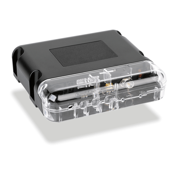
Page 6: Qube300 Hardware
Qube300 Hardware To allow for quicker and easier installations, Navman To ensure professional installation, Navman Wireless Wireless designed an all-in-one antenna system that provides an install hardware kit for all new Qube includes both GPS and cellular components built into systems. - Page 7 Port Cable Port B (RJ45) The Navman Wireless Qube300 is an Automatic Vehicle Location unit (AVL) that is installed into fleet vehicles. It communicates with a server and allows vehicle information to be stored and monitored. It is a combined GPS (Global Positioning System) and communications product that contains: Power Harness •...
- Page 8 Security Cover T-10S Security Screws T-10S Torx Screwdriver Required...
- Page 9 Power Harness Red* - Constant +12/24V • RED wire – Uninterrupted Power Source (3A fuse) Pink* - Ignition • PINK wire – Primary Ignition /Switched Source (3A fuse) Black - Ground • BLACK wire – Chassis Ground *These connections must be fused (3A) *Power Harness prepped using the Install Kit...
-
Page 10: Identifying Correct Wires
Identifying the Correct Wires 1. Remove any interior/under dash trim necessary to gain access to vehicle’s wiring as well as all areas where interconnecting wire harnesses will need to be located. 2. Attach fuse holders to the Constant and Ignition wires of the Qube’s harness. 3. - Page 11 Identifying the Correct Wires Vehicle’s Constant Power wire The correct wire will have battery voltage +12V (or +24V) present at all times, even when the ignition key is in off position or removed. Connect Qube’s red wire here. Vehicle’s Ignition wire The correct wire will have +12V (or +24V) present only when -- the key is in ON position, during cranking and while motor is running.
-
Page 12: Poke & Wrap Solderless Connections
Poke & Wrap solderless Connections The recommended method of connecting wires is by soldering. As an alternative, when working inside the cab or any weatherproof environment, a “Poke & Wrap” method for solder-less connections will be acceptable. During the “Poke & Wrap” procedure use extreme caution not to allow any exposed wires to come into direct/indirect contact with the vehicle’s chassis or other exposed wires. -
Page 13: Chassis Ground Connection
Chassis Ground Connection • Connect the Qube’s Ground wire (black) to vehicle’s chassis. • For a solid connection, use a ring tongue terminal connector, star washer and a self-tapping screw • Do not ground under existing bolts that hold brackets or panels in place. •... -
Page 14: Mounting The Antenna
Mounting the Antenna GPS/Cell Combination Antenna *View from under the dash • Exposed install: Using the supplied double-sided tape pad, mount the antenna to the bottom corner of the windshield. Make sure the correct side of antenna is facing out, into the sky. •... -
Page 15: Mobile Data Terminal: M-Nav800
Mobile Data Terminal: M-Nav800 Cradle Suction Mount Power Adaptor Mnav plugs into Data Port on Qube300 Power/Data Cable M-Nav800 Optional Panavise hard-mount bracket Route the M-Nav800 Power/Data cable from the Qube to the top of dashboard, where M-Nav800 will be mounted. - Page 16 Mobile Data Terminal: M-Nav800 4 Screws 2 Screws Install Zip Tie *In-Line Power Adaptor Optional: 2 screws for permanent mount...
-
Page 17: Conex Sensor Monitoring
ConEx Sensor Monitoring... - Page 18 ConEx Sensor Monitoring (cont.) Digital Inputs DI-1 to DI-4 +12V Dome Light Door Pin (+) Digital IN +12V Dome Light Door Pin (-) Digital IN...
- Page 19 ConEx Sensor Monitoring (cont.) Digital Outputs DO-1 & DO-2 The digital outputs will pull to ground and sink a maximum current of 250ma when activated. The outputs have over-current trip protection and, if tripped, the output must be changed to OFF or have a power cycle to reset the current trip.
- Page 20 ConEx Sensor Monitoring (cont.) Multi I/O-1 & I/O-2 Each Multi I/O can be configured in one of 3 different operating modes: Digital Input, Digital Output, or Analogue Input.
-
Page 21: Qube Power Up Procedure
Qube Power Up Procedure When the installation is complete, perform the following steps in the order they are listed to bring the device online promptly Diagnostic LED’s Green – Power (On/Off/Sleep) Red – Cell (Online/Offline) 1. Ensure vehicle is outside and has Orange –... -
Page 22: Verification
Verification • Verify vehicle is outside and has clear view of sky for the Live Test. • Access RIMU auto verification system using your smartphone or other smart device at https://onlineavl2sup-us.navmanwireless.com/AVL3WebSysadmin. • If you do not have a username and password please contact Navman Wireless Support at us.dispatch@navmanwireless.com or 877-778-2478 for verification. -
Page 23: Completing The Installation
Completing the Installation • Mount the Qube to an existing wire harness with strong zip-ties or to sheet metal using screws. Position the Qube with the LEDs facing down (LEDs visible for troubleshooting and Qube4 protection from water ingress). • Complete the installation by securing all wires with zip-ties, away from any moving parts or sharp metal edges. -
Page 24: Driver Id System
DRIVER ID SYSTEM... - Page 25 Driver ID Hardware Qube300 Driver ID Reader: Mounts in dash near driver Beeper: Do not block or cover Driver ID Key Fob: Attach to key-ring Driver ID Module: Mount behind dash Serial Data Cable: Plug into Qube300 RJ45 port...
- Page 26 Driver ID Installation • The Driver ID System allows the vehicle operator to log-in and log-out of the vehicle’s tracking system • Driver ID System works with Qube300 • Requirements: – The Driver ID Reader receiver must be installed in a location that is easily accessible to the driver of the vehicle and where the driver can see the LED light located on the top of the receiver, –...
- Page 27 TROUBLESHOOTING...
- Page 28 Troubleshooting Qube300 Installation Symptom: Qube is not powering up (All LEDs Off) (Keep in mind, during initial installation, improper ignition wire connection may prevent the Qube from waking up/coming online) 1. Cycle ignition key ON-OFF-ON to attempt to wake up the Qube. If all three Qube’s diagnostic LEDs do not come on, proceed to next step.
- Page 29 Troubleshooting Qube300 Installation continued Symptom: Qube is not reporting in RIMU (Cellular Connectivity Issues – Red LED Off) (Keep in mind, the Qube may not be reporting in RIMU because it could be out of Cell Network Coverage. As soon as the vehicle goes thru an ignition cycle in an area with good coverage, all data will back-populate.)
- Page 30 Troubleshooting Qube300 Installation continued Symptom: Qube is reporting to RIMU but shows invalid location (GPS Fix Issues – Amber LED Off) (Keep in mind, the Qube may not be reporting correct GPS location or repeating last known location because the Qube’s antenna does not have clear view of sky, is obstructed or defective) 1.
- Page 31 Troubleshooting M-Nav Installation Power Cycle/Cold Reset procedure for M-Nav800 Hold the power button down for at least 8 seconds, device will reboot. Hardware Swap Procedure: determining faulty piece of hardware 1. Verify that the Qube is functional and reporting to Director. 2.
-
Page 32: Dimensions And Specifications
Dimensions and Specifications: Qube300... -
Page 33: Technical Support
Technical support Technical Support Department Hours: Monday – Friday 7am – 7pm (Central Time) e-mail: us.support@navmanwireless.com Toll Free Phone # 877.778.2478 Local Phone # 847.832.6950... -
Page 34: Global Positioning System (Gps)
Global Positioning System (GPS) Global Positioning System (GPS) is a space-based global navigation satellite system (GNSS) that provides reliable location and time information in all weather and at all times and anywhere on or near the Earth. As a national resource, it is maintained by the United States government and is freely accessible by anyone with a GPS receiver. -
Page 35: Disclaimer
Disclaimer Although Navman Wireless’s goods, services, and software can be useful as a part of a logistics and/or property management program, Navman Wireless makes no warranty whatsoever that its goods, services, or software will prevent or mitigate any theft, misappropriation, injury, delay, or other adverse condition. Navman Wireless’s goods, services, and software are not designed, intended, authorized, or warranted to be suitable for use or resale as control equipment in, or for other applications related to, hazardous or critical environments requiring fail-safe performance, such as in the operation of nuclear facilities, aircraft navigation or communications systems, air traffic control, life support, weapons systems, or other application in which the failure of a product could...
Need help?
Do you have a question about the Qube300 and is the answer not in the manual?
Questions and answers