Table of Contents
Advertisement
Advertisement
Table of Contents

Related Manuals for TELETRAC NAVMAN Qtanium 400


Summary of Contents for TELETRAC NAVMAN Qtanium 400
- Page 1 Qtanium 400 INSTALLATION MANUAL...
-
Page 2: Table Of Contents
Qtanium 400 | Installation Manual Contents OVERVIEW ......................... 5 HARDWARE ....................... 6 ..................6 THER OMPONENTS EQUIRED ....................6 OWER ABLE PTIONS I/O C ............6 ABLES FOR PTIONAL DDITIONAL ONNECTIONS MOUNTING LOCATIONS ..................... 7 ..................7 NTENNA OUNTAIN OCATION 400 M ................ - Page 3 Qtanium 400 | Installation Manual...
- Page 4 Qtanium 400 | Installation Manual Disclaimer It is the Owner’s sole responsibility to install and use the Qtanium 400 (the Product) in a manner that will not cause accidents, personal injury or property damage. For the purpose of this notice, “Owner”, “you”...
-
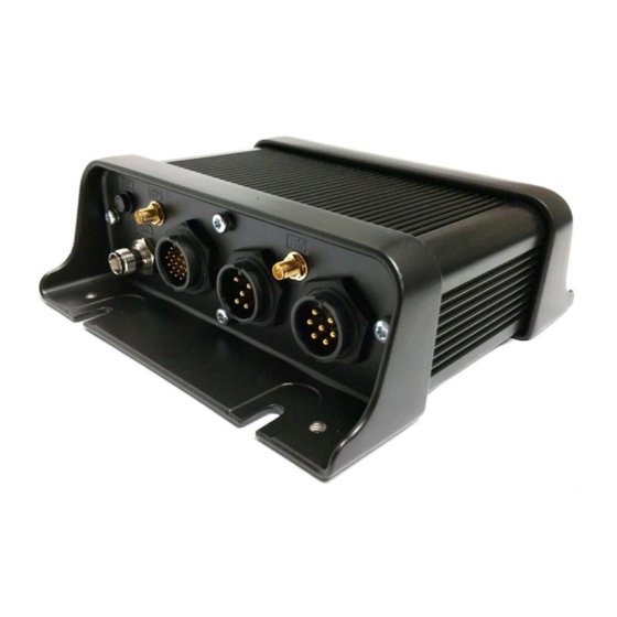
Page 5: Overview
Qtanium 400 | Installation Manual Overview The Qtanium 400 is a ruggedized Automatic Vehicle Location (AVL) unit that is installed into heavy duty vehicles (assets) such as those used for construction. It communicates with a server and allows information about the asset to be stored and monitored. -
Page 6: Hardware
4 mounting magnets Qtanium 400 Quick Install Card Note If desired, you can mount the Qtanium 400 using high-powered magnets such as M5 or equivalent (not supplied). Other Components Required You also need the following components before starting the installation: ... -
Page 7: Mounting Locations
The Qtanium 400 is rated up to 70°C but Teletrac Navman recommends that you choose a mounting location that minimises exposure to extreme temperatures. Also be aware that,... - Page 8 Qtanium 400 | Installation Manual due to the battery chemistry, battery operation will be impaired at high temperatures; in particular, it will not charge when the temperature reaches, or exceeds, 45°C. need to check ratings.
-
Page 9: Installation
7. Check that the antenna cables are long enough to reach between your chosen locations for the Qtanium 400 and the antennas. 8. Check that any other cables are long enough to connect the Qtanium 400 to any other optional devices or sensors. -
Page 10: Mount The Qtanium 400
If mounting holes are required, use grommets to ensure that the asset remains waterproof. After you have run the Qtanium 400 power cable, mount the Qtanium 400 securely on - or in - the asset using 4 self-tapping screws or 4 nuts and bolts. -
Page 11: Connect The Power Cable
1. Unscrew and retain the cover over the power port, then plug in the power cable and tighten the locking screw. 2. If you want to connect any auxiliary devices to the Qtanium 400, see section Error! Reference source not found.. Otherwise, remove the cover over the 18-Way cable connector and replace it with the one removed from the power connector, to create a waterproof and dustproof seal. -
Page 12: Connect The Power Cable/Built-In Ips Unit
Warning Failure to install the IPS according to these instructions may create an alternate path from the asset’s chassis to the negative battery post (through the casing and wiring of the Qtanium 400). This may result in large currents flowing through the Qtanium wiring, resulting in equipment damage and possible fire. -
Page 13: Connect The External Battery Backup Or Solar Panel (Optional)
Qtanium 400 | Installation Manual 2. If you want to connect any auxiliary devices to the Qtanium 400, see section 4.8. Otherwise, remove the blanking cover over the 18-Way cable connector and replace it with the one removed from the power connector, to create a waterproof and dustproof seal. -
Page 14: Connect Any Optional Equipment
Note The backup battery must operate at the same voltage as the main power supply used by the Qtanium 400. For example, if the Qtanium 400 is powered from 24 V DC, the backup battery must be 24 V DC too. - Page 15 Qtanium 400 | Installation Manual...
-
Page 16: Digital Outputs
Qtanium 400 | Installation Manual Negative Switching Configuration A negative switching input requires a Ground switching input; that is, an open circuit to Earth (or vice versa). When configured as for negative switching, the input state is considered ON when it becomes low. -
Page 17: Multi I/O-1 & I/O-2
Qtanium 400 | Installation Manual 4.8.3 Multi I/O-1 & I/O-2 Each Multi I/O can be configured in one of three different operating modes: Digital Input Digital Output Analogue Input Note When the satellite modem is enabled, Multi I/O-2 cannot be used. -
Page 18: Connect The 7-Way Cable (Optional)
Qtanium 400 | Installation Manual 4.8.4 Connect the 7-Way Cable (Optional) To connect the 7-Way cable to the Qtanium 400, unscrew the blanking cover over the 7- Way cable connector then push the 7-Way cable onto the connector and hand-tighten the locking screw. -
Page 19: Connection To A Quake Satellite Modem
4.8.7 Connection to a Quake Satellite Modem If you want to connect the Qtanium 400 to a Quake Satellite Modem, you need the 18-Way satellite modem cable. Satellite Modem for Qube 4 and Qtanium 400 Installation Manual. Note When using the satellite modem, be aware that some of the I/O will be reserved for satellite use. -
Page 20: Test The Installation With Onlineavl2/Director
Note We recommend using a mouldable plastic sealant such as COAX-SEAL® around the antenna connectors if the asset is used in a very dusty or very wet environment. Although the Qtanium 400 has an IP-67 rating, it is considered best practice to protect the RF connectors in this manner. -
Page 21: Apply The Tamper-Evident Seal
4.11 After you have checked the installation and are satisfied that it is correct: 1. Attach blanking covers to any unused ports on the Qtanium 400, if necessary. 2. Apply Tamper-Evident Seal Liquid (inspector’s lacquer) to all fuse holders, the ground screw, and all connectors and blanking covers on the Qtanium 400, as shown. -
Page 22: Troubleshooting
OnlineAVL2/DIRECTOR, and check OnlineAVL2/DIRECTOR for vehicle activity. 3. The Qtanium 400 may need to be reset. Perform a Cold Reset using the shipping plug (see the following section), start the engine, ping (Query), and wait up to 10 minutes then check for any activity in OnlineAVL2/DIRECTOR. - Page 23 7. Remove the shipping plug from the 18-Way connector then re-install the 18-Way cable (if used) or replace the blanking cover. 8. Start the engine and wait 1-5 minutes for the Qtanium 400 to reboot. Qtanium 400 with shipping plug inserted into 18-way connector...
-
Page 24: Dimensions
Qtanium 400 | Installation Manual Dimensions The mounting hole in each corner has a diameter of 5mm. -
Page 25: Specifications
Qtanium 400 | Installation Manual Specifications CELLULAR Data Support GSM/GPRS/HSPA/CDMA 1XRTT Operating Bands: MHz (Band) GSM/GPRS 850/900/1800/1900 CDMA/1Xrtt 800/1900 HSPA/UMTS 800(VI)/850(V)/900(VIII)/ 1700(IV)/1900(II)/2100(I) 3GPP Release 7 Transmitter Power: GSM/GPRS 850/900 32.5 1800/1900 29.5 CDMA/1xRTT 800 1900 HSPA/UMTS (all bands) HSPA data rates 5.76 Mbps upload/7.2 Mbps download... - Page 26 Qtanium 400 | Installation Manual ELECTRICAL Operating Voltage 7-32 VDC (momentary) 9-30 VDC (start-up, operating) Power Consumption 3mA @ 12V (deep sleep) 20mA @ 12V (idle with IP connection) 70mA @ 12V (active tracking GPS off cell enabled) Back Up Battery...
- Page 27 Qtanium 400 | Installation Manual PRODUCT ACCESSORIES 18-way Qtanium shipping plug Qtanium 400 3-way power cable Qtanium 400 4-way power cable Qtanium 18-way Serial/1-wire cable Qtanium 7-way I/O cable Dallas 1-wire temperature sensors ...
Need help?
Do you have a question about the Qtanium 400 and is the answer not in the manual?
Questions and answers