Table of Contents
Advertisement
Quick Links
Operating Instructions and Parts Manual
22" and 25" Open-End Drum Sanders
Models JWDS-2244, JWDS-2550
JET
427 New Sanford Road
LaVergne, Tennessee 37086
Ph.: 800-274-6848
www.jettools.com
This .pdf document is bookmarked
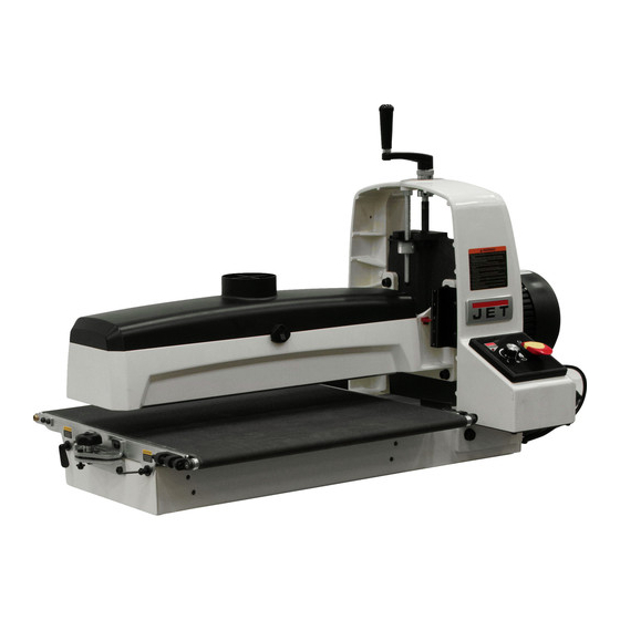
Model JWDS-2550 shown with optional closed stand
and optional infeed/outfeed tables
Part No. M-723540B
Edition 2 03/2019
Copyright © 2018 JET
Advertisement
Table of Contents

Related Manuals for Jet 723540B


Summary of Contents for Jet 723540B
- Page 1 22” and 25” Open-End Drum Sanders Models JWDS-2244, JWDS-2550 Model JWDS-2550 shown with optional closed stand and optional infeed/outfeed tables 427 New Sanford Road LaVergne, Tennessee 37086 Part No. M-723540B Ph.: 800-274-6848 Edition 2 03/2019 www.jettools.com Copyright © 2018 JET...
-
Page 2: Important Safety Instructions
Do not use this drum sander for other than its area and non-glare, overhead lighting. intended use. If used for other purposes, JET 19. Keep the floor around the machine clean and disclaims any real or implied warranty and holds free of scrap material, oil and grease. -
Page 3: About This Manual
Additional knowledge may be obtained from experienced users or trade articles. Whatever accepted methods are used, always make personal safety a priority. If there are questions or comments, please contact your local supplier or JET. JET can also be reached at our web site: www.jettools.com. -
Page 4: Table Of Contents
3.0 Table of contents Section Page 1.0 IMPORTANT SAFETY INSTRUCTIONS ....................... 2 2.0 About this manual ............................3 3.0 Table of contents ............................4 4.0 Specifications ..............................6 5.0 Features and Terminology ..........................8 6.0 Setup and assembly ............................9 ... - Page 5 15.5.3 (OPTIONAL) 723551 Infeed/Outfeed Tables for JWDS-2550 – Parts List .......... 35 15.6.1 Depth Stop Assembly for JWDS-2244/-2550 * – Exploded View ............36 15.6.2 Depth Stop Assembly for JWDS-2244/-2550 * – Parts List ..............36 15.7.1 (OPTIONAL) Closed Stand Assembly for JWDS-2550 – Exploded View ........... 37 ...
-
Page 6: Specifications
4.0 Specifications Table 1 Model number JWDS-2244 JWDS-2550 Sander/conveyor 723540B 723550B Stock numbers Sander/conveyor/open stand 723540OSK 723550OSK Sander/conveyor/closed stand 723544CSK Open stand 723540OS 723550OS Accessories Closed stand 723544CS (separate Folding Infeed/outfeed tables 723541 723551 purchase unless Digital readout 723552 indicated... - Page 7 L=length, W=width, H=height, Dia=diameter The specifications in this manual were current at time of publication, but because of our policy of continuous improvement, JET reserves the right to change specifications at any time and without prior notice, without incurring obligations.
-
Page 8: Features And Terminology
5.0 Features and Terminology The illustration below shows the major components and features of the JWDS-2244/2550 Sanders. These are referenced throughout the manual and will help to familiarize you with the operation and functions of the machine. Figure 5-1: features... -
Page 9: Setup And Assembly
Read and understand the entire contents of this manual before attempting set- up or operation! Failure to comply may cause serious injury. NOTE: Figures in this manual may show Sander with stand, extension tables and/or depth stop assembly. These optional accessories depending upon your model, and are purchased separately. -
Page 10: Assembling Stand
Figure 6-3: Assembly of Sander and OPTIONAL Infeed/Outfeed Tables 6.3 Assembling stand 6.6 Folding infeed/outfeed tables (OPTIONAL) An open stand is provided standard with the JWDS- 2244 Sander. An open or closed stand is available See Figure 6-3. as an optional accessory (separate purchase) for The sander must be bolted to the stand or a work the JWDS-2550 Sander. -
Page 11: Dust Collection
(TIP: If you are using an after-market abrasive, use particularly if stock being sanded is bowed, warped a new JET-supplied abrasive as a template to or otherwise inconsistent. Also, if stock slips on quickly cut a new strip. Alternatively, a diagram is conveyor, the tables may be positioned too high. -
Page 12: Electrical Connections
Release fastener lever to secure end of strip. sander comes with a plug designed for use on a circuit with a grounded outlet that looks like the one Begin wrapping abrasive around drum. The pictured in Figure 7-1. tapered edge of strip end should follow as closely as possible to edge of drum. -
Page 13: Extension Cords
8.0 Adjustments 8.1 Drum Height Control Drum height and depth of cut are controlled by height adjustment handle (B, Figure 6-3). Rotating handle clockwise lowers drum, counterclockwise raises it. One revolution of handle will move drum approximately 1/16” (or 1/4 turn = approx. 1/64”), as shown on label below handle. -
Page 14: Infeed/Outfeed Table Adjustment (Optional)
Excessive belt tension can result in bent rollers, bent brackets, and/or premature wearing of bushings or conveyor belt. Figure 8-3: belt take-up screw 8.5.2 Belt tracking adjustment A belt tracks correctly when it moves centrally on the Figure 8-1 conveyor rollers without drifting to either side. Tracking adjustments are made while conveyor belt 8.4 Infeed/Outfeed Table Adjustment is running. -
Page 15: Tension Roller Adjustment
Open dust cover and remove abrasive strip lower table at outboard end slightly by turning from drum. knob (C). Insert gauge (A, Figure 8-4) between drum and Repeat this process until the ridge is eliminated conveyor table at outboard side. and entire board is sanded. -
Page 16: Operations
9.0 Operations and familiarity with the machine before doing finish work. Before using the drum sander, review the previous A combination of several variables will determine sections on initial set-up and adjustment. Before proper depth of cut to use, including the following: operating, make sure an abrasive strip is mounted Abrasive type and grit size. -
Page 17: Maximum Performance Tips
depend on a number of factors, including type of adjustments to fit the job at hand. Following is a list stock, grit and depth of cut used, and whether the of useful tips which can help you improve stock is fed directly in line with the conveyor table or performance of your sander. -
Page 18: User-Maintenance
9.6.6 Face frames and raised panel Lubricate conveyor bushings as needed, and doors check for wear. Lubricate elevating leadscrew (A, Figure 10-1) It is very important to have the proper abrasive as needed. contact when doing this type of sanding. If the machine is set to take an excessive depth of cut, the ... -
Page 19: Conveyor Belt Replacement
10.3 Conveyor belt replacement 10.4 Commutator brush inspection Disconnect sander from power source/unplug. To maintain motor efficiency, inspect the two carbon brushes every two months, or more frequently if Raise drum to highest position. sander is heavily used. Stalling or loss of power may be a symptom of worn carbon brushes. -
Page 20: Tracker Kit
Install second tracker opposite the first. Use 11.0 Tracker kit both trackers unless the second one does not fit in conveyor or unless conveyor belt is damaged. Stock No.: PM2244-213 Turn conveyor table right-side up and reposition Trackers dramatically reduce tracking adjustments it onto sander. -
Page 21: Abrasives
When cleaning, also pre-cut lengths or in the convenient Ready-To-Cut brush the stick crumbs from the drum while it is still pre-marked box. Your JET dealer can recommend rotating. the best choice for your application. In some cases, heavily loaded areas can be 12.1 Selecting drum abrasives... -
Page 22: Troubleshooting Jwds-2244,-2550 Drum Sanders
13.0 Troubleshooting JWDS-2244,-2550 Drum Sanders Symptom Possible Cause Correction * Drum motor won’t start No incoming current. Check connections at plug or circuit panel. when switch is activated. Safety key missing from switch. Install safety key. Low voltage. Check power line for proper voltage. Open circuit in motor or loose Inspect all lead connections on motor for connection. - Page 23 Symptom Possible Cause Correction * Sander burns wood. Abrasive strip is overlapped. Re-wrap abrasive strip. Abrasive is loaded. Clean abrasive. Depth of cut excessive for fine grit. Use coarser grit or reduce depth of cut. Feed rate too slow. Increase feed rate. Abrasive is worn.
-
Page 24: Optional Accessories
Non-proprietary parts, such as fasteners, can be found at local hardware stores, or may be ordered from JET. Some parts are shown for reference only, and may not be available individually. -
Page 25: Jwds-2244/-2550 Head Assembly - Exploded View
15.1.1 JWDS-2244/-2550 Head Assembly – Exploded View... -
Page 26: Jwds-2244 Head Assembly - Parts List
15.1.2 JWDS-2244 Head Assembly – Parts List Index No Part No Description Size 1 ....JWDS2244-101 ..Dust Hood ...................... 1 ....JWDS2550-101 ..Dust Hood ...................... 1 2 ....JWDS2244-102 ..Socket Head Cap Screw ......... M6-1.0P x 16L ....8 3 .... - Page 27 ....LM000342 ....ID Label, JWDS-2244 (not shown) ..............1 ....LM000343 ....ID Label, JWDS-2550 (not shown) ..............1 ....JET-113 ..... JET Logo (not shown)..........113x47mm ....1 ....JWDS1632-196 ..Control Panel Label (not shown) ..............1...
- Page 28 Index No Part No Description Size ....JWDS1632-197 ..Left Parallel Adjust Label (not shown) ............1 ....JWDS1632-198 ..Right Parallel Adjust Label (not shown) ............1 ....LM000238 ....Warning Label (not shown) ................1...
-
Page 29: Optional) Digital Readout For Jwds-2244/-2550 - Exploded View
15.2.1 (OPTIONAL) Digital Readout for JWDS-2244/-2550 – Exploded View 15.2.2 (OPTIONAL) Digital Readout for JWDS-2244/-2550 – Parts List Index No Part No Description Size ....723552 ...... Drum Sander DRO Assembly (includes #1 thru 9) .......... 1 ....TS-1503021 ....Socket Head Cap Screw ......... M6-1.0P x 10L ....4 2 .... -
Page 30: Jwds-2244/-2550 Conveyor Table Assembly - Exploded View
15.3.1 JWDS-2244/-2550 Conveyor Table Assembly – Exploded View... -
Page 31: Jwds-2244 Conveyor Table Assembly - Parts List
15.3.2 JWDS-2244 Conveyor Table Assembly – Parts List Index No Part No Description Size 1 ....JWDS2244-201 ..Belt Motor ..............1/30HP 115V ....1 ....JWDS1632-201-1 ..Carbon Brush (not shown) ................2 2 ....F010839 ....Socket Head Flat Screw .......... #10 x 32UNC x 1/2IN L 4 3 .... -
Page 32: Open Stand Assembly For Jwds-2244/-2550 - Exploded View
15.4.1 Open Stand Assembly for JWDS-2244/-2550 – Exploded View... -
Page 33: 723540Os Open Stand Assembly For Jwds-2244 - Parts List
15.4.2 723540OS Open Stand Assembly for JWDS-2244 – Parts List Index No Part No Description Size ....723540OS ....Open Stand Assembly for JWDS-2244 (includes #1-11) ....... 1 1 ....JWDS1632-301 ..Leg ......................... 4 2 ....JWDS2244-302 ..Short Rail ..............11-3/4”L ......2 3 .... -
Page 34: Optional) Infeed/Outfeed Tables For Jwds-2244/-2550 - Exploded View
15.5.1 (OPTIONAL) Infeed/Outfeed Tables for JWDS-2244/-2550 – Exploded View... -
Page 35: Optional) 723541 Infeed/Outfeed Tables For Jwds-2244 - Parts List
15.5.2 (OPTIONAL) 723541 Infeed/Outfeed Tables for JWDS-2244 – Parts List Index No Part No Description Size ....723541 ...... Infeed/Outfeed Table Kit, JWDS-2244 (includes #1-13)......... 1 1 ....JWDS2244-401 ..Extension Table ..................... 2 2 ....TS-1504031 ....Socket Head Cap Screw ......... M8-1.25P x 16L ..16 3 .... -
Page 36: Depth Stop Assembly For Jwds-2244/-2550 * - Exploded View
15.6.1 Depth Stop Assembly for JWDS-2244/-2550 * – Exploded View 15.6.2 Depth Stop Assembly for JWDS-2244/-2550 * – Parts List Index No Part No Description Size ....723553 ...... Depth Stop Assembly (#1 thru 12) ..............1 ....JWDS2244-601 ..Special Nut ....................1 2 .... -
Page 37: Optional) Closed Stand Assembly For Jwds-2550 - Exploded View
15.7.1 (OPTIONAL) Closed Stand Assembly for JWDS-2550 – Exploded View 15.7.2 (OPTIONAL) Closed Stand Assembly for JWDS-2550 – Parts List Index No Part No Description Size ....723544CS ....Closed Stand Assembly (#1 thru 14) ............... 1 ....JOSS-S-245 ....Door Latch ..................... 1 2 .... -
Page 38: Electrical Connections For Jwds-2244/-2550
16.0 Electrical Connections for JWDS-2244/-2550 POTENTIOMETER CIRCUIT BOARD LOAD2 LINE2 White POWER IN Black Green LOAD1 LINE1 GROUND White Black Black White Green SANDING MOTOR White TO BELT MOTOR Black... -
Page 39: Warranty And Service
JET sells through distributors only. The specifications listed in JET printed materials and on official JET website are given as general information and are not binding. JET reserves the right to effect at any time, without prior notice, those alterations to parts, fittings, and accessory equipment which they may deem necessary for any reason whatsoever. - Page 40 427 New Sanford Road LaVergne, Tennessee 37086 Phone: 800-274-6848 www.jettools.com...
Need help?
Do you have a question about the 723540B and is the answer not in the manual?
Questions and answers