Jet 16-32 Plus Operating Instructions And Parts Manual
Drum sander
Hide thumbs
Also See for 16-32 Plus:
- Operating and parts manual (36 pages) ,
- Operating instructions manual (21 pages) ,
- Specifications (4 pages)
Table of Contents
Advertisement
This .pdf document is bookmarked
Operating Instructions and Parts Manual
Drum Sander
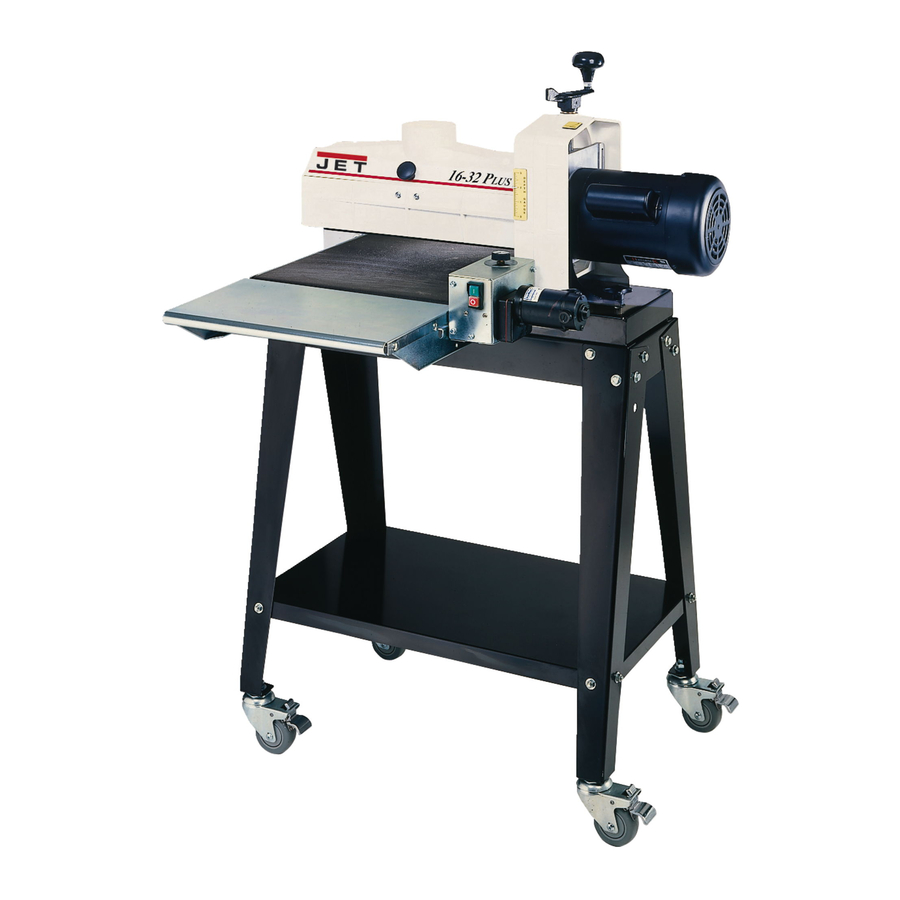
Model 16-32 Plus
shown with optional casters (98-0130) and infeed/outfeed tables (98-1601)
JET
427 New Sanford Road
LaVergne, Tennessee 37086
Part No. M-629004
Ph.: 800-274-6848
Revision B5 07/2015
www.jettools.com
Copyright © 2015 JET
Advertisement
Table of Contents

Related Manuals for Jet 16-32 Plus


Summary of Contents for Jet 16-32 Plus
- Page 1 This .pdf document is bookmarked Operating Instructions and Parts Manual Drum Sander Model 16-32 Plus shown with optional casters (98-0130) and infeed/outfeed tables (98-1601) 427 New Sanford Road LaVergne, Tennessee 37086 Part No. M-629004 Ph.: 800-274-6848 Revision B5 07/2015 www.jettools.com...
-
Page 2: Warranty And Service
JET sells through distributors only. The specifications listed in JET printed materials and on official JET website are given as general information and are not binding. JET reserves the right to effect at any time, without prior notice, those alterations to parts, fittings, and accessory equipment which they may deem necessary for any reason ®... -
Page 3: Table Of Contents
Table of Contents Warranty and Service ..........................2 Warning ..............................4 Introduction ............................. 6 Specifications ............................6 Features and Terminology ........................7 Unpacking ............................... 8 Contents of Boxes ..........................8 Assembling the Stand ..........................9 ... -
Page 4: Warning
5. Do not use this sander for other than its intended use. If used for other purposes, JET disclaims any real or implied warranty and holds itself harmless from any injury that may result from that use. - Page 5 21. Make your workshop child proof with padlocks, master switches or by removing starter keys. 22. Give your work undivided attention. Looking around, carrying on a conversation and “horse-play” are careless acts that can result in serious injury. 23. Maintain a balanced stance at all times so that you do not fall or lean against moving parts. Do not over-reach or use excessive force to perform any machine operation.
-
Page 6: Introduction
Introduction This manual is provided by JET covering the safe operation and maintenance procedures for a JET Model 16-32 Plus Drum Sander. This manual contains instructions on installation, safety precautions, general operating procedures, maintenance instructions and parts breakdown. This machine has been designed and constructed to provide consistent, long-term operation if used in accordance with instructions set forth in this manual. -
Page 7: Features And Terminology
Features and Terminology The illustration below shows the major components and features of the 16-32 Plus Sander. These are referenced throughout the manual and will help to familiarize you with the operation and functions of the machine. Figure 1... -
Page 8: Unpacking
Unpacking Open boxes and check for shipping damage. Report any damage immediately to your distributor and shipping agent. Do not discard any shipping material until the Drum Sander is assembled and running properly. Compare the contents of your boxes with the following parts list to make sure all parts are intact. -
Page 9: Assembling The Stand
Assembling the Stand (Refer to Figure 4. If further clarification is needed, consult the parts breakdown on page 28.) Tools required for Stand assembly: Ratchet wrench with 1/2” socket 1. Assemble legs (H) to outside of Short Rails (L) using carriage bolts (N) and flanged lock nuts (O). Finger tighten only. -
Page 10: Assembling The Sander
(Figure 6). [NOTE:The four holes at the center of the Figure 6 long rails are not used with the 16-32 Plus.] 6. Fasten base to stand (from beneath) with the four screws and flat washers that you removed from the plywood boards. -
Page 11: Infeed And Outfeed Tables (Optional Accessory)
IMPORTANT: The conveyor belt has been over- tensioned for shipping purposes. It must be re- tensioned before operating the sander! See “Conveyor Belt Tension/Tracking” on page 16. Infeed and Outfeed Tables (Optional Accessory) The sander should be bolted to the stand or a work table when using these table extensions. -
Page 12: Dust Collection
Dust Collection Dust collection is mandatory for a safe work environment and extended abrasive life. The 16- 32 Plus is equipped with a 4” dust collection port at the top of the dust cover. It is designed to be used with standard 4” dust collection hose connected to a high volume dust collector (minimum 400 to 600 cfm). - Page 13 5. Mark the trailing end of the strip where it crosses the right (inboard) end of the drum (Figure 13). 6. Remove the abrasive strip from the drum, and cut a taper as was done with the starting edge (see Figure 10). Note: The taper on the remaining roll can be used as the taper for the starting edge of the next strip to be cut.
-
Page 14: Grounding Instructions
Grounding Instructions Electrical connections must be made by a qualified electrician in compliance with all relevant codes. This machine must be properly grounded to help prevent electrical shock and possible fatal injury. In the event of a malfunction or breakdown, grounding provides a path of least resistance for electric current to reduce the risk of electric shock. -
Page 15: Extension Cords
Recommended Gauges (AWG) of Extension Cords Extension Cords Extension Cord Length * If an extension cord is necessary, make sure the cord rating is suitable for the amperage listed on the machine's motor plate. An undersized cord Amps feet feet feet feet feet... -
Page 16: Dust Cover Latch
Dust Cover Latch The dust cover latch prevents the dust cover from accidentally opening. To release the latch, press inward on the dust cover knob (D, Figure 21). This will cause the dust cover center to flex and release the latch. Note that the dust cover latch can be adjusted in or out by loosening the screw (E, Figure 21). -
Page 17: Sanding Drum Alignment
3. Remove the four bolts attaching conveyor assembly to base. Lift up and slide conveyor out to the side of the machine. 4. Set conveyor on motor side and slide conveyor belt off the end of the conveyor bed. 5. Reverse process for installation of new belt. Sanding Drum Alignment The sanding drum must be aligned parallel to the conveyor bed for proper machine operation. -
Page 18: Drum Height Control Adjustment
Fine-Tuning Drum Alignment (for sanding boards wider than the drum) NOTE: Perform this alignment after you are familiar with sander operation. This is an operational test. When sanding boards wider than the drum, drum alignment is critical and must be exactly level to slightly high on the outboard end to prevent ridges from forming on the board. -
Page 19: Tension Roller Alignment
4. Loosen set screws on collar (Figure 28). 5. Slide collar upward against housing so that all vertical free-play of height adjustment screw is eliminated. An easy method of doing this is to use a block of wood on top of the motor mount slide and under the collar, while lowering the drum with the height adjustment... -
Page 20: Operation
NOTE: The use of a carrier or backer board (not 1. Repeat “Tension Roller Alignment” except provided), is recommended for cuts 1/16” or raise the sanding drum only 1/4 turn of the less. This is a flat board, usually of wood or height adjustment handle. -
Page 21: Tips For Maximum Performance
Tips for Maximum Performance The SandSmart controller continuously monitors the load on the drum motor, and automatically The versatility designed into the 16-32 Plus regulates the speed of the conveyor motor to drum sander allows it to be used for a wide maintain the highest feed rate without overload. -
Page 22: Maintenance
Sanding Imperfect Stock mineral streaks in the stock, more even wear of abrasive strips, potentially faster feed rates, and When sanding stock with a cup or crown, place lighter loads on the motor. Note that to get the the crown up. This will stabilize the stock to help best final finish, however, the stock should be prevent tipping or rocking during sanding. -
Page 23: Tracker Kit (98-0080)
8. Install second Tracker opposite the first. Use Tracker Kit (98-0080) both Trackers unless the second one does not fit in conveyor or if conveyor belt is Trackers dramatically reduce tracking adjust- damaged. ments of conveyor belts. They are already installed your sander. -
Page 24: Troubleshooting
Troubleshooting Trouble Probable Cause Remedy Check plug connection. Make sure fuse is not blown/circuit breaker is not No incoming power. tripped. Push the circuit breaker Sander will not start. button on the sander motor to re-set. Switch is malfunctioning. Replace switch. Conveyor motor Reduce depth of cut;... - Page 25 Trouble Probable Cause Remedy Tension rollers too high. Lower tension rollers (see page 19). Board slips on Excessive feed rate. Reduce feed rate. conveyor belt. Dirty or worn conveyor belt. Replace conveyor belt. Adjust belt tension. If necessary, Improper conveyor belt tension. reduce depth of cut and/or feed rate.
-
Page 26: Abrasives
It is important to select the proper grit of following the manufacturer’s directions. Cleaning abrasives for the type of sanding being sticks are available from your JET dealer. When performed to achieve maximum sanding results. cleaning, also brush the stick crumbs from the As with any sanding operation, first begin drum while it is still rotating. -
Page 27: Optional Accessories
Optional Accessories 98-0130 Locking Casters, set of 4 98-1601 Infeed/Outfeed Tables 60-6036 Ready-To-Wrap Abrasive Strip, 36 Grit, (4 wraps in a box) 60-6060 Ready-To-Wrap Abrasive Strip, 60 Grit, (4 wraps in a box) 60-6080 Ready-To-Wrap Abrasive Strip, 80 Grit, (4 wraps in a box) 60-6100 Ready-To-Wrap Abrasive Strip, 100 Grit, (4 wraps in a box) -
Page 28: Conveyor And Motor Assembly
Conveyor and Motor Assembly... -
Page 29: Parts List: Conveyor And Motor Assembly
Parts List: Conveyor and Motor Assembly Index No. Part No. Description Size 1 ....3237359....Gear Motor ..........90 VDC ......1 2 ....72-6014 ....Large Strain Relief ................1 3 ....72-5336 ....Cord Set ............115V – 75” ......1 4 .... -
Page 30: Drum Head Assembly
Drum Head Assembly... -
Page 31: Parts List: Drum Head Assembly
Parts List: Drum Head Assembly Index No. Part No. Description Size 34 ..... 70-4101A ....Motor ............1-1/2HP, 110-120V ... 1 ....70-4101-1 ....Motor Fan (not shown) ................1 ....70-4101-2 ....Motor Fan Cover (not shown) ............... 1 ....C-300125A ....Capacitor (not shown)........300MFD, 125VAC ..... 1 35 ..... -
Page 32: Parts List: Infeed/Outfeed Tables (Optional Accessory)
91 ..... 11-1000-04 ....Lock Washer, Internal Tooth ......1/4” ........2 92 ..... TS-0561011 .....Hex Nut ............1/4”-20 ......2 93 ..... TS-0680021 .....Flat Washer ..........1/4” ........2 94 ..... 98-0010 ....Handle Kit (includes index #46,48,49) (not shown) ........95 ..... -
Page 33: Parts List: Stand Assembly
Parts List: Stand Assembly Index No. Part No. Description Size 1A .... 40-4040 ....Left Leg ....................2 1B .... 40-4041 ....Right Leg (with TufTool holder) ............. 2 2 ....40-4042 ....Long Rail ....................2 3 ....40-4043 ....Short Rail ..................... 2 4 .... -
Page 34: Electrical Connections
Electrical Connections... - Page 36 427 New Sanford Road LaVergne, Tennessee 37086 Phone: 800-274-6848 www.jettools.com...
Need help?
Do you have a question about the 16-32 Plus and is the answer not in the manual?
Questions and answers