Jet JSG-96 Operating Instructions And Parts Manual
Hide thumbs
Also See for JSG-96:
- Operating instructions manual (29 pages) ,
- Operating instructions and parts manual (24 pages) ,
- Operating instructions and parts manual (24 pages)
Table of Contents
Advertisement
Quick Links
Advertisement
Table of Contents

Related Manuals for Jet JSG-96


Summary of Contents for Jet JSG-96
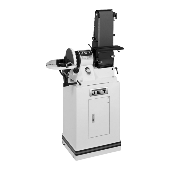
- Page 1 This .pdf document is bookmarked Operating Instructions and Parts Manual Benchtop Disc/Belt Sander Model JSG-96 (shown with optional closed stand 708597) 427 New Sanford Road LaVergne, Tennessee 37086 Part No. M-708595 Ph.: 800-274-6848 Revision H 10/2015 www.jettools.com Copyright © 2015 JET...
-
Page 2: Warranty And Service
JET sells through distributors only. The specifications listed in JET printed materials and on official JET website are given as general information and are not binding. JET reserves the right to effect at any time, without prior notice, those alterations to parts, fittings, and accessory equipment which they may deem necessary for any reason ®... -
Page 3: Table Of Contents
Belt Sander Assembly Breakdown ........................19 Parts List for the Belt Sander Assembly ......................20 Open Stand Assembly (Optional) ........................22 Closed Stand Assembly (Optional) ......................... 23 Parts List for Closed Stand (Optional) ......................24 JSG-96 Wiring Diagram ............................24... -
Page 4: Warning
Warning Wear eye protection. Always keep guards in place and in proper operating condition. Do not operate the machine without the guards for any reason. This disc/belt sander is intended to be used with wood and wood products only. Use of this disc/belt sander and a dust collector with metal products is a potential fire hazard. - Page 5 • USE RECOMMENDED ACCESSORIES. The use of accessories and attachments not recommended by JET may cause hazards or risk of injury to persons. • NEVER STAND ON A MACHINE. Serious injury could occur if the machine is tipped.
-
Page 6: Grounding Instructions
If there are any questions or comments, please contact either your local supplier or JET. JET can also be reached at our web site: www.jettools.com. -
Page 7: Specifications
Gross Weight (approx.) ..........................100 Lbs. The above specifications were current at the time this manual was published, but because of our policy of continuous improvement, JET reserves the right to change specifications at any time and without prior notice, without incurring obligations. -
Page 8: Unpacking
Unpacking Open shipping container and check for shipping damage. Report any damage immediately to your distributor and shipping agent. Do not discard any shipping material until the Sander is assembled and running properly. Compare the contents of your container with the following parts list to make sure all parts are intact. -
Page 9: Closed Stand Assembly (Optional)
1. Move the sander to a workbench or one of JET’s optional stands. Bolt the unit firmly to secure in place. (See page 7 for hole spacing.) JET’s closed stand uses four 3/8”x3” hex cap bolts, four 3/8”... -
Page 10: Adjustments
Adjustments Sanding Belt Table Adjustment Always disconnect the sander from the power source before servicing or making any adjustments. Failure to comply may cause serious injury. 1. Place a square on the sanding belt table with one edge along the graphite pad, or sanding belt (Figure 4). -
Page 11: Horizontal Sanding Workstop
Horizontal Sanding Workstop 1. Loosen the socket head cap screw (A, Fig. 7) so that the sanding belt can be rotated to the horizontal position. 2. Rotate the sander until the stop (B, Fig. 7) contacts the sander base. Tighten the socket head cap screw. -
Page 12: Belt Tracking Adjustment
Belt Tracking Adjustment 1. Connect the machine to the power source. One time quickly turn the machine “ON” and “OFF”. This will allow you to view the belt’s tendency to run down the middle, to the right, or to the left. The belt should run centered on the sanding drums. -
Page 13: Sanding Disc Replacement
4. If the miter slot is not parallel, loosen the two socket head cap screws (A, Fig. 13) and adjust for parallel. Tighten the two screws when the adjustment is complete. 5. Always maintain a gap of approximately 1/16” between the table edge and disc. Once the table is square and parallel to the disc adjust the 90°... -
Page 14: Dust Collection
Dust Collection 1. Hook the sander to a dust collector using a 4” diameter hose and clamp (A, Fig. 16). JET offers a wide variety of hoses, adapters and dust collectors. 2. Loosen the wing nut (B, Fig. 16) and pull the gate (C, Fig. -
Page 15: Troubleshooting
Troubleshooting Trouble Probable Cause Remedy Sander unplugged from wall, or motor. Check all plug connections. Replace fuse, or reset circuit breaker. Sander will not start Fuse blown, or circuit breaker tripped. Make sure supply circuit matches amperage rating on motor plate. Cord damaged. -
Page 16: Disc Sander Assembly Breakdown
Disc Sander Assembly Breakdown... -
Page 17: Parts List For The Disc Sander Assembly
Parts List for the Disc Sander Assembly Index No. Part No. Description Size 1 ....JSG96-101A....Base....................... 1 2 ....JSG96-102 ....Motor......................1 ....JSG96-102A....Starting Capacitor (not shown) ........ 150MFD, 125VAC ..1 ....JSG96-102B....Running Capacitor (not shown) ....... 20uF, 250VAC ....1 3 .... - Page 18 Index No. Part No. Description Size 58 ....JSG96-158 ....Holder-Small (Running Capacitor) ..............1 59 ....JSG96-159 ....Holder-Big (Starting Capacitor)..............1 60 ....JSG96-160 ....Plate....................... 1 ....JSG96-MGA ....Miter Gauge Assembly (Items 38, 46 thru 52) ..........1 ....
-
Page 19: Belt Sander Assembly Breakdown
Belt Sander Assembly Breakdown See Disc Sander Breakdown... -
Page 20: Parts List For The Belt Sander Assembly
Parts List for the Belt Sander Assembly Index No. Part No. Description Size 1 ....JSG96-201 ....Bracket......................1 2 ....TS-0208071 ....Hex Socket Cap Screw ..........5/16x1-1/4 ..... 1 3 ....JSG96-203 ....Pin........................1 4 ....JSG96-204 ....Fixed Plate ..................... 1 5 .... - Page 21 Index No. Part No. Description Size 61 ....JSG96-261 ....Serrated Plate ....................2 62 ....JSG96-262 ....Phillips Tap Screw ........... M3x10 ......4 63 ....JSG96-263 ....Lock Washer ............¼ ........1 64 ....JSG96-264 ....Set Screw ..............1/4x1-1/2 ....... 1 ....
-
Page 22: Open Stand Assembly (Optional)
Open Stand Assembly (Optional) Long "Stand Top" overlaps Short "Stand Top" Index No. Part No. Description Size 1 ....JSG96-401 ....Stand Top (front and rear, short) ..............2 2 ....JSG96-402 ....Stand Top (left and right, long) ..............2 3 .... -
Page 23: Closed Stand Assembly (Optional)
Closed Stand Assembly (Optional) -
Page 24: Parts List For Closed Stand (Optional)
24 ....TS-0060131 ....Hex Head Screw* ............ 3/8x3 ......4 25 ....TS-0561031 ....Hex Nut* ..............3/8 ......... 4 ....STRIPE-1-3/4 .... JET Stripe ..............1-3/4 ....... per ft....JSG96-HKC ....Hardware Kit for Closed Stand (includes items marked with *)
Need help?
Do you have a question about the JSG-96 and is the answer not in the manual?
Questions and answers