Table of Contents
Advertisement
This Manual is Bookmarked
Operating Instructions and Parts Manual
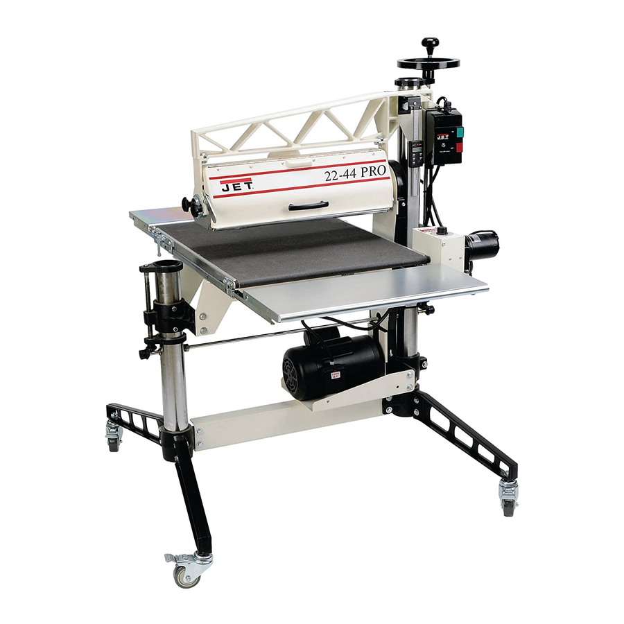
Drum Sander
Model 22-44 Pro
Deluxe model shown (with casters and infeed/outfeed tables)
WMH TOOL GROUP
2420 Vantage Drive
Elgin, Illinois 60123
Part No. M-638003
Ph.: 800-274-6848
Revision A 4/06
www.wmhtoolgroup.com
Copyright © WMH Tool Group
Advertisement
Table of Contents
Troubleshooting

Related Manuals for Jet 22-44 Pro


Summary of Contents for Jet 22-44 Pro
- Page 1 This Manual is Bookmarked Operating Instructions and Parts Manual Drum Sander Model 22-44 Pro Deluxe model shown (with casters and infeed/outfeed tables) WMH TOOL GROUP 2420 Vantage Drive Elgin, Illinois 60123 Part No. M-638003 Ph.: 800-274-6848 Revision A 4/06 www.wmhtoolgroup.com...
-
Page 2: Warranty And Service
WARRANTY AND SERVICE WMH Tool Group, Inc., warrants every product it sells. If one of our tools needs service or repair, one of our Authorized Service Centers located throughout the United States can give you quick service. In most cases, any of these WMH Tool Group Authorized Service Centers can authorize warranty repair, assist you in obtaining parts, or perform routine maintenance and major repair on your JET tools. -
Page 3: Table Of Contents
Contents of the Shipping Container ...8 Assembly...9 Install Stand Legs...9 Table Support Screws ...9 Install Handwheel ...10 Install Conveyor Table...10 Infeed and Outfeed Tables (Optional Accessory)...10 Leveling the Sander ...11 Dust Collection...11 Installing Abrasives ...12 Grounding Instructions...14 Extension Cords...15 Adjustments...15 Switch Lockout ...15 Dust Cover...15... -
Page 4: Warning
5. Do not use this sander for other than its intended use. If used for other purposes, WMH Tool Group disclaims any real or implied warranty and holds itself harmless from any injury that may result from that use. - Page 5 29. Keep your hands clear when feeding parts onto the conveyor. The part will be forced down as it begins to feed, causing a pinching action between the part and the conveyor bed. Never reach into a running machine. Turn off sander and disconnect from power before attempting to retrieve parts from beneath the drum.
-
Page 6: Introduction
This manual is provided by WMH Tool Group covering the safe operation and maintenance procedures for a JET Model 22-44 Pro Drum Sander. This manual contains instructions on installation, safety precautions, general operating procedures, maintenance instructions and parts breakdown. This machine has been designed and constructed to provide years of trouble free operation if used in accordance with instructions set forth in this manual. -
Page 7: Features And Terminology
Features and Terminology The illustration below shows the major components and features of the 22-44 Pro Sander. These are referenced throughout the manual and will help to familiarize you with the operation and functions of the machine. Figure 1... -
Page 8: Unpacking
Report any damage immediately to your distributor and shipping agent. Do not discard any shipping material until the Drum Sander is assembled and running properly. Compare the contents of your container with the following parts list to make sure all parts are intact. -
Page 9: Table Support Screws
Install Stand Legs The sander is heavy; use caution when lifting. 1. Raise the sander from the floor using a forklift, hoist or an assistant. (Place hoist straps through the carriage arm or below the table mounting brackets. If using a forklift, fork below the table mounting brackets. -
Page 10: Install Handwheel
2. Remove conveyor table from packaging, and place it on the mounting brackets of the stand. The gear motor should be on the right, or inboard side of the sander as shown in Figure 7. 3. Secure the conveyor bed with four 3/8”x1”... -
Page 11: Leveling The Sander
Dust collection is mandatory for a safe work environment and extended abrasive life. The sander is equipped with a 4” dust collection port at the back of the dust cover. It is designed to be used with standard 4” dust collection hose connected to a high volume dust collector with a minimum capacity of 600 CFM. -
Page 12: Installing Abrasives
Installing Abrasives An 80-grit abrasive strip is already installed on the drum of your sander. Page 28 offers information on the types of abrasive and their recommended uses. Proper attachment of the abrasive strip to the drum is critical to achieving top performance from your drum sander. - Page 13 8. You can use your fingers to work the infeed take-up fastener, but it will be more convenient to use the TUFTool supplied with your sander. Hold the TUFTool with the red end pointing away from you (Figure 15) and insert its hook into the outside hole of the fastener lever (see Figure 17).
-
Page 14: Grounding Instructions
As received from the factory, your drum sander is intended for use on a 20 amp, 110V dedicated circuit, which has an outlet and a plug that look like the ones illustrated in Figure 18. The sander cannot be rewired to voltages other than factory settings. -
Page 15: Table Height Control
The edges will pop out when the dust cover is pulled from the carriage leg brackets. Reverse this procedure to re-install the dust cover. - Page 16 • The set screws in the table supports have been loosened and readjusted (see page 9). • The sander has been leveled (page 11). • Moving parts of the height adjustment mechanism are well lubricated, including miter gears, columns, adjusting screws.
-
Page 17: Depth Gauge Calibration
Proceed as follows: First inspect the alignment with a gauge of some kind. The following procedure uses a steel straight edge as a gauge. See Figure 26. - Page 18 Tighten pinch bolt in motor support and tighten two lower screws in belt guard (Figure 27). Fine-Tuning Drum Alignment The 22-44 Pro is equipped with a drum adjuster mechanism that allows easy fine tuning or changing of drum alignment without repeating the intial drum alignment procedure.
-
Page 19: Conveyor Belt Tension And Tracking
Test alignment with scrap wood approximately 6” wide by 24” to 40” long. Run board through sander sideways so that end of board extends beyond end of drum. Rotate board 180° and sand the other end. If a ridge is... -
Page 20: Trackers
Then allow time for the belt to react to the adjustments before proceeding further. Try to avoid over adjustments. Trackers The sander comes equipped with “Trackers”, ceramic guides that reduce the amount of adjustments needed to keep the conveyor belt tracked (centered) on the conveyor bed. See Figure 32. -
Page 21: Tension Roller Adjustment
Step 2: Now repeat Step 1 on the right (inboard) side of conveyor. Compare the measurements from side to side. If they are not equal, loosen one of the brackets that hold the roller in place. Tip this bracket until the distance between the roller and the straight-edge are equal from side to side, then tighten the bracket. -
Page 22: Replacing V-Belt
If clicking noises in the bearings are a problem, rotating solution replacement, as follows: 1. Unplug sander from power source. 2. Loosen the set screws in the bearing collar (Figure 39). Leave the set screw wrench in one of the set screws. Then rotate the drum within the bearing and tighten the set screws. -
Page 23: Replacing Drum Bearings
See page 18. Replacing Drum Bearings If the bearings are squealing or are loose, they may need replacing. 1. Unplug sander from power source and remove dust cover. 2. Raise conveyor table until the sanding drum rests on the conveyor. -
Page 24: Operation
3. Start drum. 4. Start conveyor and select feed rate. 5. Feed stock through machine. To feed stock through the 22-44 Pro, rest and hold the board to be sanded on the conveyor belt, allowing the conveyor belt to carry the board into the drum. - Page 25 Be aware that the sander will remove cups and crowns in the workpiece; consider this when measuring and processing stock to the same thickness.
-
Page 26: Maintenance
Maintenance Before doing maintenance on the machine, disconnect it from the electrical supply by pulling out the plug or switching off the main switch! Failure to comply may cause serious injury. Keeping the Machine Clean For best results, make cleaning the machine a regular shop procedure. -
Page 27: Tracker Kit (98-0080)
6. On the underside of the conveyor bed, there are U-channels welded to the bed. The Tracker is positioned on the inside of the first U-channel on the infeed side of sander (the U-channel closest to the rubber covered drive roller and gear motor). The back of the Tracker is magnetized and will stick to the side wall of the conveyor bed. -
Page 28: Abrasives
Abrasives The abrasive material you choose will have a substantial effect on the performance of your sander. Variations in paper type, weight, coating and durability all contribute to achieving your desired finish. JET Abrasives are available in Ready-To- Wrap pre-cut lengths or in the convenient Ready-To-Cut pre-marked box. -
Page 29: Troubleshooting: Motor And Electrical Problems
Adjust tension (see page 19). Allow motor to cool and re-set overload button. Connect sander to a dedicated circuit. Have a certified electrician correct any shop wiring problem. Use a shorter or heavier gauge extension cord (see Figure 20). - Page 30 Trouble Probable Cause Conveyor belt out of adjustment. Drive or driven roller needs adjusting. Conveyor belt tracks Conveyor belt worn or defective. to one side, or oscillates from side to Drive roller worn, bent, or varies in side. diameter side to side. Roller bushings elongated due to excessive wear.
-
Page 31: Troubleshooting: Operational Problems
Ripples in sanded Excessive feed rate. surface. Excessive depth of cut. (Uniformly spaced ripples). Sander vibration. Tension rollers set too low. Sniping of wood Stock not supported properly during (gouging near end of infeed or outfeed. board). Conveyor drive roller or driven roller higher than conveyor belt surface. - Page 32 Trouble Probable Cause Conveyor belt is loose. Excessive depth of cut. Gouging of wood. Wood slipping on conveyor due to lack of contact. Abrasive is too fine. Line or groove in Inconsistent feed rate. stock. Unsanded ridge along length of piece Grit has been removed from backing.
-
Page 33: Optional Accessories
Optional Accessories 98-2201 Infeed/Outfeed Tables 98-0130 Casters (set of 4) 80-2910 Dust Hose Adaptor, 4” reduce to 2-1/2” 60-2000 Ready-To-Wrap Assortment Package (one each of 30, 80, and 120 grit) 60-2024 Ready-To-Wrap Abrasive Strip, 24 Grit, (4 wraps in a box) 60-2036 Ready-To-Wrap Abrasive Strip, 36 Grit, (4 wraps in a box) -
Page 34: Stand Assembly
Stand Assembly... -
Page 35: Parts List: Stand Assembly
Parts List: Stand Assembly Index No. Part No. Description Size 1...31-0027... Handwheel Assembly ... 8”O.D., 1/2” I.D... 1 2...10-8903... Socket Set Screw ... 5/16”x3/8” ... 2 3...BB-R8ZZ... Bearing..4 4...80-4015... Plastic Cap ... 3” ... 2 5...10-2804... Socket Set Screw ... 1/4”-20x1/2” ... 10 6...30-1110... -
Page 36: Drum Head Assembly
Drum Head Assembly... -
Page 37: Parts List: Drum Head Assembly
Parts List: Drum Head Assembly Index No. Part No. Description Size 1...30-0002W ... Drum Carriage Arm..1 2...30-0015W ... Clamp Jaw..1 3...12-0005... Hex Nut ... 3/8”-16 ... 1 4...6861201... Wrought Washer... 5/16” ... 6 5...10-9206... Hex Head Bolt ... 3/8”-16x1-1/4” ... 1 6...30-0059... -
Page 38: Conveyor And Motor Assembly
Conveyor and Motor Assembly... -
Page 39: Parts List: Conveyor And Motor Assembly
Parts List: Conveyor and Motor Assembly Index No. Part No. Description 1...72-2250-01... Knob..1 2...40-4017W ... Control Housing Bracket ..1 3...JSG96-135... On/Off Drum Switch..1 4...73-1255... Variable Speed Conveyor Controller (includes #1 and 52)... 1 5...72-2120... Receptacle ... 115 Volt ... 1 6...72-6101... -
Page 40: Infeed And Outfeed Tables (98-2201) - Optional Accessory
Infeed and Outfeed Tables (98-2201) – Optional Accessory Index No. Part No. Description Size 1...40-0329... Infeed/Outfeed Table ..2 2L ...40-0327... Mounting Bracket (LH) ..2 2R ...40-0328... Mounting Bracket (RH) ..2 3...10-9103... Hex Head Bolt ... 5/16”-18x3/4” ... 2 4...12-0152... -
Page 41: Electrical Connections
Electrical Connections... - Page 42 NOTES...
- Page 44 WMH Tool Group 2420 Vantage Drive Elgin, Illinois 60123 Phone: 800-274-6848 www.wmhtoolgroup.com...
Need help?
Do you have a question about the 22-44 Pro and is the answer not in the manual?
Questions and answers