Table of Contents
Advertisement
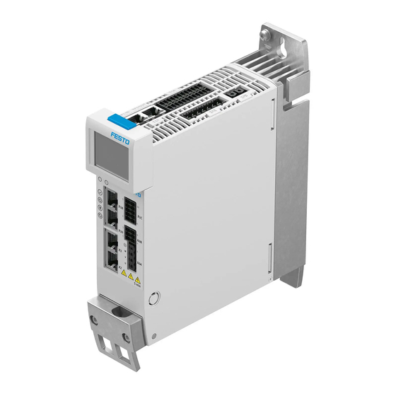
CMMT-AS-C2/3/5-11A-P3-...-S1
Servo drive
Instructions | Installation, Safety subfunction
8113981
201907a
[8113983]
Translation of the original instructions
EnDat
®
, EtherCAT
®
, EtherNet/IP
®
PROFIBUS PROFINET
®
, TORX
®
are registered trademarks of the respective trade
mark owners in certain countries.
1
About this document
1.1
Target group
The document is targeted towards persons who mount and operate the product. It
is additionally targeted towards individuals who are entrusted with the planning
and application of the product in a safetyrelated system (safety manual in
accordance with EN 61508).
1.2
Applicable documents
All available documents for the product è www.festo.com/pk.
The user documentation for the product also includes the following documents:
Designation
Contents
Product instruction manual
Installation, safety subfunction
Product descriptions
Detailed description of assembly, installation
Detailed description of safety subfunction
Description/online help plugin
Plugin:
–
Functions and operation of the software
–
Initial commissioning assistant
Firmware functions:
–
Configuration and parameterisation
–
Operating modes and operational functions
–
Diagnostics and optimisation
Bus protocol/control:
–
Device profile
–
Controller and parameterisation
Festo Automation Suite online
–
Function of the Festo Automation Suite
help
–
Management and integration of devicespecific plugins
CDSB instruction manual
General functions of the operator unit
Tab. 1 User documentation for the product
1.3
Product version
This documentation refers to the following version of the device:
–
Servo drive CMMTAS...S1, revision R01 and higher, see product labelling
1.4
Product labelling
•
Observe the specifications on the product.
The product labelling is located on the right side of the device. The product
labelling enables identification of the product and shows the following informa
tion:
Product labelling (example)
CMMTASC211AP3ECC000V000S1
5340821 J302 Rev 00
Main input: 200 V AC 10 % ... 480 V AC + 10 %
48 ... 62 Hz 2 A
RMS
Motor out: 3 x 0 ... input V AC 0 ... 599 Hz
1.7 A
0.8 kW
RMS
T
: 40 – 50 °C
AMB
SCCR: 10 kA
cUL restriction: only for use in WYE 480 V/277 V
supply sources
IP10/20
Festo AG & Co. KG
Ruiter Straße 82
73734 Esslingen
Germany
+49 711 3470
www.festo.com
, DR. JOHANNES HEIDENHAIN
®
, Hiperface
Meaning
Order code
Part number, serial number, revision (Rev)
Technical Data on power supply (alternating cur
rent supply connection)
Technical data for the motor output (output
voltage, max. output frequency, nominal current,
nominal output power)
Ambient temperature (T
)
AMB
SCCR (short circuit current rating)
Operation on power supply systems with SCCR £
100 kA
è
Degree of protection; without mating plug/with
mating plug [X9A] attached
Product labelling (example)
MAC: XXXXXXXXXXXX
RREMFTOKC20181054
See manual for internal overload protection and
required external circuit breaker
Data matrix code, 123456789ABC...
Festo AG & Co. KG
DE73734 Esslingen
Made in Germany
Tab. 2 Product labelling (example)
Warning symbols on the front of the product
The following warning symbols are located on the front of the product:
8113981
®
, PI
Fig. 1 Warning symbols on the front side of the product (example CMMTAS...EC)
General meaning
Attention! Hot surface
Attention! General danger point
Attention! Dangerous voltage
5 minutes (wait)
Tab. 3 Meaning of the warning symbols
Warnings on the product
The following warnings are attached to the right side of the device:
Warnings on the product (en, fr)
CAUTION
Risk of Electric Shock! Do not touch electrical connectors for
5 minutes after switching power off! Read manual before
installing! High leakage current! First connect to earth!
AVERTISSEMENT
Risque du choc électrique! Une tension dangereuse peut ètre
présentée jusqu'à 5 minutes aprés avoir coupé l'alimentation !
Lire le manuel avant installation ! Courant de défaut élevée ! Relier
tout d´abord à la terre !
DANGER
Risk of Electric Shock! Disconnect power and wait 5 minutes
before servicing.
Risque du choc électrique! Débranchez l'alimentation et attendez
5 min. avant de procéder à l'entretien.
WARNING
Hot surface Risk of burn!
ATTENTION
Risque de temperature élevée !
Tab. 4 Warnings on the product
Meaning
First MAC address of the device for Ethernet com
munication
KC mark certificate (test mark for Korea)
Reference to the existing user documentation,
which contains information on overload protec
tion and the necessary external line safety switch
(circuit breaker).
Product key as a data matrix code and an
11character alphanumeric code
Manufacturer
Manufacturer's address
Manufactured in Germany
1 Attention! Hot surface
2 Attention! General danger point
3 Attention! Dangerous voltage
4 5 minutes (wait)
Meaning with the CMMT-AS-...
Metallic housing parts of the device can reach high temperatures
during operation. In the event of a fault, internal components may
become overloaded. Overloading of components can result in
high temperatures and the release of hot gases.
The touch current in the protective earthing conductor can exceed
an alternating current of 3.5 mA or a DC current of 10 mA.
The minimum cross section of the protective earthing conductor
must comply with the local safety regulations for protective earth
ing conductors for equipment with high leakage current.
The product is equipped with DC link capacitors, which store dan
gerous voltage for up to 5 minutes after the power supply is
switched off. Do not touch power connections for 5 minutes after
the power supply is switched off.
After the power supply is switched off, wait at least 5 minutes
until the DC link capacitors have discharged.
Meaning
Caution
Risk of electric shock! Do not
touch electrical connections for
5 minutes after switching
power off! Read manual before
installing! High leakage current
after PE! First connect device to
protective earthing!
Danger
Risk of electric shock! Discon
nect power and wait 5 minutes
before servicing.
Warning
Hot surface – danger of burns!
Advertisement
Table of Contents

Subscribe to Our Youtube Channel
Related Manuals for Festo CMMT-AS-C2-11A-P3 S1 Series


Summary of Contents for Festo CMMT-AS-C2-11A-P3 S1 Series
- Page 1 Fig. 1 Warning symbols on the front side of the product (example CMMTAS...EC) Applicable documents General meaning Meaning with the CMMT-AS-... All available documents for the product è www.festo.com/pk. Attention! Hot surface Metallic housing parts of the device can reach high temperatures during operation. In the event of a fault, internal components may The user documentation for the product also includes the following documents: become overloaded.
- Page 2 The motors must fulfil the requirements of EN 6180052 appendix D.3.5 and filter to PE D.3.6 and of EN 602041. Motors approved or specified by Festo for the CMMTAS – Install the product in a suitable control cabinet. The minimum degree of pro...
- Page 3 Spare parts è www.festo.com/spareparts. – All available documents for the product and current versions of the firmware and commissioning software è www.festo.com/sp. Service Contact your regional Festo contact person if you have technical questions è www.festo.com. Product overview Scope of delivery Component Number Servo drive CMMTAS...
- Page 4 Safety sub-functions – The #SBCA request switches off the power to the signals BR+/BR. 5.3.1 Function and application – The #SBCB request switches off the power to the signal BREXT. The servo drive CMMTAS...S1 has the following safetyrelated performance fea In the event of a power failure in the logic voltage supply of the servo drive, power tures: is also cut off to the brake outputs.
- Page 5 CMMTAS devices. mentation. For adjacent thirdparty devices, Festo recommends a distance of at least 10 mm (surface temperature of thirdparty device max. 40 °C). The double mating plug for crosswiring of the connection [X9A] protrudes by approx. 4 … 5 mm over the right side of the device.
- Page 6 coupled in the DC link circuit must be protected by means of a common mains WARNING! fuse. Risk of injury from electric shock in the event of incomplete insulation at the • Only use line safety switches and fuses that have the relevant approval and power connections [X6A], [X9A] and [X9B].
- Page 7 Connection examples Connection plan, 3-phase mains connection 1 PE connection (earthing screw) Fig. 6 PE connection (earthing screw) Information on EMC-compliant installation A mains filter is integrated into the device. The mains filter fulfils the following tasks: – Guarantees the device’s immunity to interference –...
- Page 8 The safety request is passed on to the servo drive on 2 channels via the inputs [X1A] Function Description #STOA and #STOB at the connection [X1A]. This safety request results in the #STOB Control input Safe torque off, 2channel switchoff of the driver supply to the servo drive’s power output stage. channel B The safety relay unit can use the STA diagnostic output to monitor whether the #SBCA...
- Page 9 ECN 1113/EQN 1125 ECN 1123/EQN 1135 Max. cable length 3 m EnDat 2.1 Only in conjunction with Festo motors from the Tab. 23 Requirements for the connecting cable series EMMSAS that have an integrated encoder with EnDat 2.1 protocol Shield connection requirements Digital incremental encoders with squarewave ROD 426 or compatible...
- Page 10 Thermal memory in the Supported, cannot be None – Only use motor cables that have been approved for operation with the Festo event of motor switch parameterised servo drive. Motor cables of other manufacturers are permitted if they meet the specified requirements.
- Page 11 Motor cable shield support on the motor side (> 11 mm … 15 mm) cable does not get crushed in Detailed information on the motorside connection with motor cables from Festo the clamping area due to excessive pressure. è Assembly instructions for the motor cable used è www.festo.com/sp.
- Page 12 Requirements for the Individual device Device compound Connection Pin Type Identifier Function connecting cable [X1A] X1A.11 #STOB Safe torque off, channel B Max. length 2 m £ 0.5 m X1A.12 #STOA Safe torque off, channel A X1A.22 DOUT Safe torque off acknowledge Tab. 37 Requirements for the connecting cable 8.10.2 [X9C], logic voltage supply Tab.
- Page 13 3 Error (example CMMTAS...EC) Preparation for commissioning 4 Ethernet interface activated [X18] For initial commissioning, you will need to have the Festo Automation Suite soft ware installed along with the CMMTAS plugin è www.festo.com/sp. 5 Communication activity [X18] 6 Sync interface activated [X10] Prepare for commissioning as follows: 1.
- Page 14 2. Send the defective product unchanged, together with a description of the accordance with EN 61508, error and application, back to Festo. 3. Check with your regional Festo contact person to clarify the conditions for the Common cause factor for return shipment.
- Page 15 CE marking (declaration of conformity In accordance with EU EMC Directive 15.3.1 Load voltage supply [X9A] è www.festo.com/sp) In accordance with EU Machinery Directive In accordance with EU Low Voltage Directive Electrical data, load voltage supply [X9A] In accordance with EU RoHS Directive CMMTAS...
- Page 16 Parameters for the power specifications CMMTAS C211AP3 C311AP3 C511AP3 Nominal voltage of mains connection [V AC] Ambient temperature (air) [°C] £ 40 Setup altitude £ 1000 Tab. 61 Parameters Power specifications during operation with the given parameters [X6A] CMMTAS C211AP3 C311AP3 C511AP3 Pulsewidth modulation frequency [kHz] Current regulator cycle time...
Need help?
Do you have a question about the CMMT-AS-C2-11A-P3 S1 Series and is the answer not in the manual?
Questions and answers