Table of Contents
Advertisement
Quick Links
Advertisement
Table of Contents

Related Manuals for TRI tool BEVELMASTER 214B


Summary of Contents for TRI tool BEVELMASTER 214B
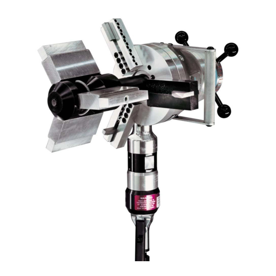
- Page 1 Operation Manual...
- Page 2 ABOUT TRI TOOL TECHNOLOGIES At Tri Tool, we are committed to your success through relentless innovation and powerful partnership. We insist on developing tools and equipment that exceed your expectations of performance, precision, safety, and durability. As a full-service engineering firm, we are here to support you every step of the way.
-
Page 3: Table Of Contents
Table of Contents Tri Tool Inc Warranty About the Manual Safety Precautions General Description Specifications Set Up and Operation Cutting Speeds anad Feeds Tool Bits Jaw Blocks, Ramps and Adapters Full Support Pad Kits Maintenance Trouble Shooting Accessories Illustrated Parts Breakdown... -
Page 4: Tri Tool Inc Warranty
TRI TOOL INC. TRI TOOL INC. Warranty LIMITED WARRANTY: All products manufactured by Seller are warranted to be free from defects in materials and workmanship under normal use. The period of this warranty shall be three years from the date of shipment for all products, except for welding and Non- Standard Products which shall be one year from the date of shipment. - Page 5 Model 214B Bevelmaster Buyer’s notice of a defective Goods must identify the specific Goods affected, and the nature of the defect. It is required when returning the defective Goods, that it is suitably packed, fully insured, and transportation and insurance prepaid in accordance with instructions issued by Seller.
-
Page 6: About The Manual
The instructions and descriptions in this manual were accurate when the manual was written. However, the information in the manual is subject to change without notice. Check for updated information before you start any job. The Tri Tool Inc. web site has the most current information. - Page 7 Model 214B Bevelmaster SAFETY GLASSES: Indicates a hazardous situation that requires the use of safety glasses. GLASSES HOT SURFACE: Indicates a hazardous situation that hot surfaces may be present. HOT SURFACE GLOVES: Indicates a hazardous situation that requires glasses. GLOVES ARC FLASH &...
-
Page 8: Safety Precautions
TRI TOOL INC. 2. SAFETY PRECAUTIONS In General Use standard safety equipment such as: hard hats, safety shoes, safety harnesses, protective clothes, and other safety devices when appropriate. Operate this tool only in accordance with specific operating instructions. WARNING: Do not override the dead-man switch on the power unit. Locking down, obstructing, or in any way defeating the dead-man switch on the power drive unit may result in serious injury. - Page 9 Before you start operating the equipment, do no-load tests and feed function checks. Tool Use Use the right tool and tool bit for the job. Contact Tri Tool to help with your application. Keep the tool bits fully engaged in the tool bit holders. Loose bits are sharp and can cause cuts or punctures.
-
Page 10: General Description
TRI TOOL INC. 3. GENERAL DESCRIPTION The Model 214B BEVELMASTER® is a portable ID mount machine tool for beveling, facing and counterboring 4" (101.6 mm) through 14" (355.6 mm) pipe. The tool is configured with an in-line feed knob and has the option for a pneumatic, electric 115V/230V heavy duty and/ or hydraulic drive motor positioned in a right angle to the lathe head. -
Page 11: Specifications
Model 214B Bevelmaster 4. SPECIFICATIONS Design and operating features The lathe accepts its own torque through the mandrel. The expanding mandrel provides fast, accurate self-centering and alignment. The lathe, provided with a convenient handle, is lightweight and easily handled by one operator. - Page 12 TRI TOOL INC. Model 214B BEVELMASTER with Air Motor attached ® Weight: 80 lbs (36.3 kg) Clearances and Dimensions Maximum Rotating Head DIA: 15.35" (389.9 mm) Length (parallel to axis of pipe): 21.25" (539.8 mm) Length Over Motor: 31.00" (787.4 mm) Maximum Width: 10.60"...
- Page 13 Wall thickness of all standard pipe schedules 1.41" (35.7 mm) maximum in the range listed. Tubing with greater wall thickness may be handled provided the I.D. is greater than 3.44" (87.4 mm ) and the O.D. is less than 14.00" (355.6 mm). Contact Tri Tool for heavier wall procedures.
- Page 14 TRI TOOL INC. Feeds Manual-Feed handle is in-line at the back of the machine. Feed Rate: .083" (2.1 mm) per revolution of the feed handle. Maximum Feed Travel: 2.00" (50.8 mm). Mounting Manually actuated draw rod expands mandrel ramps and jaw blocks.
- Page 15 Model 214B Bevelmaster MODEL 214B BEVELMASTER ® WITH ELECTRIC H.D. (HEAVY DUTY) MOTOR ATTACHED Weight: 87 lbs (39.5 kg) 21.25" (539.8 mm) 10.85" (275.8 mm) 10.60" (269.3 mm) 20.05" (509.3 mm) 15.35" (389.9 mm) Rotating DIA Figure 2: Model 214B with an Electric Motor Clearance and Dimensions Maximum Rotating Head DIA.: 15.35"...
- Page 16 Inconel and some other high temperature alloys may require special procedures as a function of wall thickness and type of end preparation. Contact TRI TOOL Inc. Engineering Department for details. Cutting Speeds...
- Page 17 Model 214B Bevelmaster Feed Manual-Feed handle is in line at the back of the machine. Feed Rate: .083” (2.1 mm) per revolution of the feed handle. Maximum Feed Travel: 2.00” (50.8 mm) Mounting Manually actuated draw rod expands mandrel ramps and jaw blocks. Drive System Gear Driven Electric Motor...
- Page 18 TRI TOOL INC. MODEL 214B BEVELMASTER ® WITH HYDRAULIC MOTOR ATTACHED Weight (Approx.): 100 lbs (45.4 kg) 21.25" (539.8 mm) 10.85" (275.6 mm) 10.60" (269.3 mm) 13.57" (344.7 mm) 15.35" (389.9 mm) Rotating DIA Figure 3: Model 214B with a Hydraulic Motor Clearance and Dimensions Maximum Rotating Head DIA: 15.35"...
- Page 19 Wall thickness of all standard pipe schedules, 1.32" (33.5 mm) maximum, in the range listed. Tubing with greater wall thickness may be handled provided the ID is greater than 3.44" (87.4 mm) and the OD is less than 14.00" (355.6 mm). Contact TRI TOOL Inc. for heavier wall procedures.
- Page 20 Maximum H.P. Speed: 155 RPM Power Requirements Requires separate hydraulic power supply. Reference the Tri Tool Inc. Model 765RVC. Flow 3 gpm (.19 L/s) - 15 gpm (.94 L/s) @ 1500 PSI (10.342 kPa) 15 gpm (.94 L/s) - 20 gpm (1.265 L/s) @ 1000 PSI (6895 kPa) Temperature Maximum Operating Temperature: 180°...
-
Page 21: Setup And Operation
When operating any/all Tri Tool Inc. equipment follow the ‘Note’ statements through the manual for equipment safety and the ‘Warning’ and/or ‘Caution’ notes for operator safety. A FRL (Filter/Regulator/Lubricator) is required to protect the warranty on all TRI TOOL INC. air or hydraulic driven tools. - Page 22 Attach the tool holders in the appropriate position. Select the tool bit(s) required to machine the pipe for the configuration desired. Use of dull or improperly designed tool bits or tool bits not manufactured by TRI TOOL Inc. may result in poor performance and may constitute abuse of this machine and therefore voids the TRI TOOL Inc.
- Page 23 Model 214B Bevelmaster The beveling tool bit should be installed in the steel tool holder. Tool Holder Cutting Edge, Tool Bit (Aluminum) Facing (Land) Cutting Edge, Tool Bit Counterbore (Deburring) Rotation Tool Holder Cutting Edge, Tool (Steel) Bit Beveling Figure 5: Tool Bit Installation When performing any multiple machining operation such as facing, beveling, and/or counterboring, the counterbore tool bit should be installed to ‘lead’...
- Page 24 TRI TOOL INC. Install the Mandrel in the Model 214B Slide the Model 214B gently onto the mandrel assembly until it comes to a solid stop against the torque acceptance keys. Rotate the Model 214B as required to engage the torque acceptance keys with the slots in the mandrel shaft.
- Page 25 Model 214B Bevelmaster Rotate the set screw as required until the torque acceptance keys are riding snugly in the slots in the mandrel shaft. Run the feed in and out to insure that the torque acceptance keys are not so tight that the feed is impaired.
- Page 26 TRI TOOL INC. Machining Sequence Electric Motor Attach the power cord to the proper AC outlet. Depress the trigger. Adjust the cutting speed by rotating the speed control dial on the trigger. Air Motor Attach the proper air supply line to the Model 214B.
- Page 27 Model 214B Bevelmaster Continue rotating the feed handle clockwise until the end of the pipe is completely machined. The axial feed rate of the tool bit is .0023” (.06 mm) for each graduation or .083” (2.11 mm) for each complete revolution of the feed handle. Continue machining until the end of the pipe has a complete prep.
- Page 28 TRI TOOL INC. Loosen the Mandrel draw nut to release the mandrel from the pipe. Slowly pull the Model 214B and the mandrel from the end of the pipe. The mandrel assembly may be left in the Model 214B and installed as a complete assembly in the next pipe to be machined.
-
Page 29: Cutting Speeds Anad Feeds
Aluminum and some thin-wall mild steel and tube with coolants. Inconel and some other high-temperature alloys may require special procedures as a function of wall thickness and type of end preparation. Contact TRI TOOL’s Engineering Department for details. Basic Feed Recommendation Use very light feed for initial cutting or until a continuous cut is established. -
Page 30: Tool Bits
TRI TOOL INC. 7. TOOL BITS Facing Tool Bit, Facing or Land Model 214B Cutting Edge Pipe Facing Tool Bit Chart Pipe or Tube Facing Tool Bit Face Range Material 3.312" ID through 14.000" ID DURABIT4 (84.1 mm ID through 355.6 mm ID) 3.312"... - Page 31 Model 214B Bevelmaster Counterbore Tool Bit, Counterbore Cutting Edge Model 214B Pipe Counterbore Tool Bit Chart Pipe or Tube 14.5° C'Bore Facing Tool Bit Counterbore Range Material Tool Bit P/N 3.328" ID through 14.000" ID 99-2908 D URAB IT4 (84.1 mm ID through 355.6 mm ID ) 3.328"...
- Page 32 TRI TOOL INC. ID Chamfer Tool Bit, ID Chamfer Cutting Edge Model 214B Pipe Chamfer and Facing Tool Bit Chart 10° ID Facing Tool Bit Pipe or Tube ID Chamfer Range Chamfer Tool Material Bit P/N 3.328" ID through 14.000" ID...
- Page 33 Model 214B Bevelmaster J-Bevel Tool Bit, J-Bevel Cutting Edge Model 214B Pipe J-Bevel Range and Facing Tool Bit Chart 25° .187R Pipe or Tube Facing Tool Bit J-Bevel Range J-Bevel Tool Material Bit P/N 3.328" ID through 12.750" ID 99-2915 D URAB IT4 (84.1 mm ID through 323.9 mm ID ) 3.328"...
- Page 34 TRI TOOL INC. Bevel Tool Bit, Bevel Cutting Edge Model 214B Pipe 37 1/2° Bevel and Facing Tool Bit Chart Pipe or Tube 37 1/2° Bevel Facing Tool Bevel and Face Range Material Tool Bit P/N Bit P/N 3.312" ID through 13.375" ID...
- Page 35 Model 214B Bevelmaster 37 1/2° Bevel Tool Bit Chart Pipe or Tube 37 1/2° Bevel Tool Bit Bevel (Only) Range Material 3.312" ID through 14.000" ID 99-3341 (84.1 mm ID through 355.6 mm ID ) 3.312" ID through 14.000" ID 99-3338 (84.1 mm ID through 355.6 mm ID ) 3.312"...
-
Page 36: Jaw Blocks, Ramps And Adapters
TRI TOOL INC. 8. JAW BLOCKS, RAMPS AND ADAPTERS Ramp Jaw Block Adapter 92-1500 Rev. 230127... - Page 37 Model 214B Bevelmaster Standard Ramp, Jaw Block Assy and Adapter Chart Jaw Block Standard Ramp Adapters ID Mounting Range Assembly (3 Req'd) (3 Req'd) (3 Req'd) 3.31" thru 4.35" 48-0520 (84.1 mm thru 110.5 mm) 4.25" thru 5.31" 48-0520 08-0185 (108.0 mm thru 134.9 mm) 5.21"...
-
Page 38: Full Support Pad Kits
TRI TOOL INC. 9. FULL SUPPORT PAD KITS Fig #. 214B Full Support Pad Assembly Figure 11: Full Support Pad Assembly Pipe ID Kit Set 8" SCH5S 05-1628 8" SCH10S 05-1629 10" SCH5S 05-1630 10" SCH10S 05-1631 12" SCH5S 05-1632 12"... - Page 39 Model 214B Bevelmaster Full Support Pad Kit Standard 214B Mandrel Mandrel Assembly Ramp Block Ramp Fig #. Pad Assembly Figure 12: Pad Assembly 05-1628 through 05-1635 Mounting Instructions for Full Support Pad Kits Attach the Pad Assembly to the mandrel by securing it to the ramp with the two designated screws that are retained inside the assembly.
-
Page 40: Maintenance
TRI TOOL INC. 10. MAINTENANCE All components should be cleaned and coated with a light film of oil after use. Use a clean, non-detergent oil, preferably SAE 10 (90 SSU) or lighter or oil as specified for the air motor. - Page 41 The air motor requires a Class 2 lubricant, viscosity of 100 to 200 SSU at 100° F (38° C) minimum aniline point of 200° F (93° C). • TRI TOOL INC. Air Tool Lubricant • Chevron – A.W. Machine Oil 32 (P/N 68-0022) •...
-
Page 42: Trouble Shooting
TRI TOOL INC. 10. TROUBLE SHOOTING Problem: The Tool Bit Chatters The tool bit is loose or overextended. The tool bit is damaged. The tool holder is too loose in the slides. The cutting speed is too fast. The clamping pads are loose on the pipe or tube. - Page 43 Model 214B Bevelmaster Problem: The Tool Holder is Not Feeding The feed pin is broken or out of position. The feed sprocket shear pin is broken. The feed screw is stripped. The feed nut is stripped. The slide rails are too tight. Problem: The Tool Bit is Diving and the BEVELMASTER is Stalling...
-
Page 44: Accessories
TRI TOOL INC. 11. ACCESSORIES The following accessories are available for use with the Model 214B BEVELMASTER ® are available from TRI TOOL Inc. • Dial Indicator Kit • Elbow Mandrel Adjustable Pin Kit • Elbow Mandrel Assembly, Small • Elbow Mandrel Kit •... -
Page 45: Illustrated Parts Breakdown
Model 214B Bevelmaster 12. ILLUSTRATED PARTS BREAKDOWN MODEL 214B BEVELMASTER (P/N 01-1141) ® 92-1500 Rev. 230127... - Page 46 TRI TOOL INC. Parts List, Model 214B BEVELMASTER (P/N 01-1141) ® Item Part Description 02-2115 BEVELER SUB-ASSY, 212B/214B 06-0528 MANDREL ASSY, 214B 49-0393 HOLDER ASSY, TOOL, STEEL 49-0995 HOLDER ASSY, TOOL, ALUM 57-0168 MOTOR ASSY, AIR, INLINE, 310RPM NOT SHOWN...
- Page 47 Model 214B Bevelmaster MODEL 214B SUB-ASSEMBLY (P/N 02-2115) 92-1500 Rev. 230127...
- Page 48 TRI TOOL INC. Parts List, Model 214B Sub-Assembly (P/N 02-2115) Item Part Description 19-0449 HOUSING, MAIN 19-0450 HOUSING, FEED 20-0391 SHAFT, MAIN 24-0781 PLATE, FEED 24-0782 PLATE, HANDLE 24-0783 PLATE, SEAL 28-0175 SEAL, SHAFT 28-0176 SEAL, EXTRUDED, 3/16" X BULK 10.50"...
- Page 49 Model 214B Bevelmaster Parts List, Model 214B Sub-Assembly (P/N 02-2115) Continued Item Part Description 33-0503 SCREW, SET, CUP POINT, 1/4-20 X .50” 33-0507 SCREW, SET, 1/4-20 X 1”, CUP PT 33-0903 SCREW, SET, HALF DOG, 1/4-20 X .31” 33-1572 SCREW, SET, 1-12 X .75” 34-0225 SHIM, BEARING 34-0226...
- Page 50 TRI TOOL INC. MANDREL ASSEMBLY (P/N 06-0528) Parts List, Mandrel Assembly (P/N 06-0528) Item Part Description 08-0185 BLOCK ASSEMBLY, JAW, AL, .609" (15.5 MM) 08-0186 BLOCK ASSEMBLY, JAW, AL, 1.096" (27.8 MM) 08-0187 BLOCK ASSEMBLY, JAW, AL, 1.583" (40.2 MM) 08-0188 BLOCK ASSEMBLY, JAW, AL, 2.070"...
- Page 51 Model 214B Bevelmaster TOOL HOLDER ASSEMBLY, STEEL (P/N 49-0393) Parts List, Tool Holder Assembly, Steel (P/N 49-0393) Item Part Description 33-0041 SCREW, CAP, 1/4-20 X 7/8 33-0057 SCREW, CAP, 5/16-18 X 1-1/4 33-0518 SCREW, SET,5 /16-18 X 3/4 CUP PT 49-0307 HOLDER, TOOL, STEEL 92-1500 Rev.
- Page 52 TRI TOOL INC. TOOL HOLDER ASSEMBLY, ALUMINUM (P/N 49-0995) Parts List, Tool Holder Assembly, Aluminum (P/N 49-0995) Item Part Description 33-0041 SCREW, CAP, 1/4-20 X 7/8 33-0057 SCREW, CAP, 5/16-18 X 1-1/4 33-0518 SCREW, SET, 5/16-18 X 3/4 CUP PT...
- Page 53 Model 214B Bevelmaster MOTOR ASSEMBLY, AIR, IN-LINE, 310 RPM (P/N 57-0168) Parts List, IN-LINE Air Motor Assembly, 310 RPM (P/N 57-0168) Item Part Description 33-0056 SCREW, CAP, 5/16-18 X 1” 57-0161 AIR MOTOR, IN-LINE, 1/2" SQ, 310 RPM 53-0046 VALVE, FLOW CONTROL, 1/2" NPT 54-0126 COUPLING, MALE QD TO 1/2"...
- Page 54 TRI TOOL INC. MOTOR ASSEMBLY, ELECTRIC, HD, 115V/230V 92-1500 Rev. 230127...
- Page 55 Model 214B Bevelmaster Parts List, Motor Assembly, Electric, HD, 115V (P/N 58-0167) Item Part Description 27-0826 ADAPTER, DRIVE 30-3143 1/2" SQUARE DRIVE 33-0055 SCREW, CAP, 5/16-18 X 7/8" LG. 33-0057 SCREW, CAP, 5/16-18 X 1 1/4" LG. 33-1874 SCREW, ANTI-ROTATION 58-0192 MOTOR, ELECTRIC, 115V, MODIFIED Parts List, Motor Assembly, Electric, HD, 230V (P/N 58-0174)
- Page 56 TRI TOOL INC. MOTOR ASSEMBLY, HYDRAULIC (P/N 56-0101) 92-1500 Rev. 230127...
- Page 57 Model 214B Bevelmaster Parts List, Motor Assembly, Hydraulic (P/N 56-0101) Item Part Description 27-0618 ADAPTER, DRIVE 27-0619 ADAPTER, HYDRAULIC MOTOR 32-0090 PIN, SHEAR 33-0061 SCREW, CAP, 5/16-18 X 2 1/4" 33-0107 SCREW, CAP, 1/2-13 X 1 1/2" 54-0002 ADAPTER 54-0333 COUPLER, QD, HYD, DRIPLESS, FEMALE 54-0334 COUPLER, QD, HYD, DRIPLESS, MALE...
- Page 58 TRI TOOL INC. KIT, FULL SUPPORT PAD, 214B (P/N 05-1628 - 05-1635) Parts List, Kit, Full Support Pad, 214B (P/N 05-1628 & 05-1629) Item No. Part No. Description 33-0144 SCREW, CAP, 3/4-10 X 1-1/2 33-0040 SCREW, CAP, 1/4-20 X 3/4...
- Page 59 Model 214B Bevelmaster Parts List, Kit, Full Support Pad, 214B (P/N 05-1630 & 05-1631) Item No. Part No. Description 33-0144 SCREW, CAP, 3/4-10 X 1-1/2 33-0040 SCREW, CAP, 1/4-20 X 3/4 33-0059 SCREW, CAP, 5/16-18 X 1-3/4 34-0757 WASHER, NYLON, .562"OD X .328"ID X.060" 44-1735 SPACER, FULL SUPPORT, SCH 5/10, 214 48-4698...
- Page 61 • Disconnect power sources before servicing or moving the equipment. • Remove all loose articles of clothing and jewelry before operating the equipment. Be Safety Conscious! 3041 Sunrise Blvd. Rancho Cordova, CA 95742 +1(916) 288-6100 • +1(800) 345-5015 www.tritool.com ©Copyright Tri Tool Inc. PN 81-0542 (04-21)
Need help?
Do you have a question about the BEVELMASTER 214B and is the answer not in the manual?
Questions and answers