
Subscribe to Our Youtube Channel
Related Manuals for ANTAIRA LNX-1802G-T


Summary of Contents for ANTAIRA LNX-1802G-T
- Page 1 16-port 10/100TX + 2-Port 10/100/1000T Mini-GBIC Combo Industrial Ethernet Switch User Manual...
- Page 2 FCC Warning This Equipment has been tested and found to comply with the limits for a Class-A digital device, pursuant to Part 15 of the FCC rules. These limits are designed to provide reasonable protection against harmful interference in a residential installation. This equipment generates, uses, and can radiate radio frequency energy.
-
Page 3: Table Of Contents
Content Introduction ..............1 Features ..............1 Package Contents ............ 2 Hardware Description ..........3 Physical Dimension ..........3 Front Panel .............. 3 Top View ..............4 LED Indicators ............4 Ports ................. 6 Cabling ..............8 Wiring the Power Inputs ......... 12 Wiring the Fault Alarm Contact ...... -
Page 4: Introduction
Introduction The 16 10/100TX + 2 10/100/1000T/Mini-GBIC Combo Industrial Switch is a cost- effective solution and meets the high reliability requirements demanded by industrial applications. Using fiber port can extend the connection distance that increases the network elasticity and performance. Features ... -
Page 5: Package Contents
Package Contents Please refer to the package content list below to verify them against the checklist. 16 10/100TX + 2 10/100/1000T/Mini-GBIC Combo Industrial Switch Pluggable Terminal Block User manual 2 wall mount plates with screws One DIN-Rail (attached on the switch) Compare the contents of the industrial switch with the standard checklist above. -
Page 6: Hardware Description
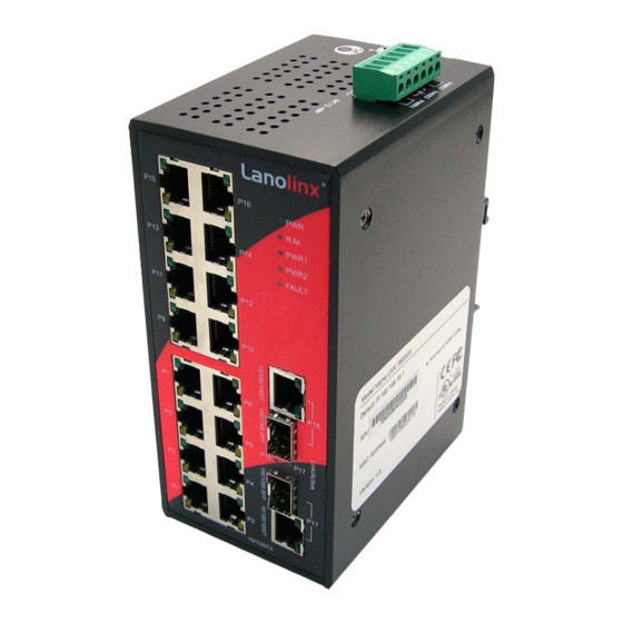
Hardware Description In this paragraph, it will describe the Industrial switch’s hardware spec, port, cabling information, and wiring installation. Physical Dimension 16 10/100TX + 2 10/100/1000T/Mini-GBIC Combo Industrial Switch dimension (W x D x H) is 72mm x 105mm x 152mm Front Panel The front panel of the 16 10/100TX + 2 10/100/1000T/Mini-GBIC Combo Industrial Switch is shown as below:... -
Page 7: Top View
Top View The top panel of the 16 10/100TX + 2 10/100/1000T/Mini-GBIC Combo Industrial Switch has one terminal block connector of two DC power inputs. Top Panel of the industrial switch LED Indicators The diagnostic LEDs located on the front panel of the industrial switch provide real-time information of system and optional status. - Page 8 PWR1 & PWR2 are both active or no power inputs Green Connected to network (Upper LED) Blinking Networking is active (Upper LED) Not connected to network (Upper LED) P1 ~ P16 Yellow Ethernet port full duplex (Lower LED) Blinking Collision of packets occurs (Lower LED) Ethernet port half duplex or not connected to (Lower LED)
-
Page 9: Ports
Ports RJ-45 ports The UTP/STP ports will auto-sense for 10Base-T/100Base-TX connections (Fast Ethernet) or 10Base-T, 100Base-TX, or 1000Base-T connections (Gigabit Ethernet). Auto MDI/MDIX means that the switch can connect to another switch or workstation without changing straight through or crossover cabling. See the figures below for straight through and crossover cable schematic. - Page 10 Straight Through Cable Schematic Cross Over Cable Schematic 2 Gigabit Copper/SFP (Mini-GBIC) combo port: The Industrial switch has two auto-detected Giga port—UTP/STP/Fiber combo ports. The Gigabit Copper (10/100/1000T) ports should use Category 5e or above UTP/STP cable for the connection up to 1000Mbps. The SFP slots supporting dual mode can switch the connection speed between 100 and 1000Mbps.
-
Page 11: Cabling
Cabling Twisted-pair segment can be established by using unshielded twisted pair (UTP) or shielded twisted pair (STP) cabling. The cable between the link partner (switch, hub, workstation, etc.) and the converter must be less than 100 meters (328 ft.) long and comply with the IEEE 802.3ab 1000Base-T standard for Category 5e or above. - Page 12 Make sure the module is aligned correctly and then slide the module into the SFP slot until a click is heard. Figure 2.9: Transceiver Inserted...
- Page 13 Second, insert the fiber cable of LC connector into the transceiver. Figure 2.10: LC connector to the transceiver To remove the LC connector from the transceiver, please follow the steps shown below: First, press the upper side of the LC connector from the transceiver and pull it out to release.
- Page 14 Second, push down the metal loop and pull the transceiver out by the plastic part. Figure 2.12: Pull out from the SFP module...
-
Page 15: Wiring The Power Inputs
Wiring the Power Inputs Please follow the steps below to insert the power wire. 1. Insert the positive and negative wires into the V+ and V- contacts on the terminal block connector. 2. To tighten the wire-clamp screws for preventing the DC wires to loose. -
Page 16: Wiring The Fault Alarm Contact
Wiring the Fault Alarm Contact The fault alarm contact is in the middle of terminal block connector as the picture shows below. Inserting the wires, it will detect the fault status which the power is failure or port link failure (for managed model) and form an open circuit. Insert the wires into the fault alarm contact (No. -
Page 17: Mounting Installation
Mounting Installation DIN-Rail Mounting The DIN-Rail is screwed on the industrial switch when out of factory. If the DIN-Rail is not screwed on the industrial switch, please see the following pictures to screw the DIN- Rail on the switch. Follow the steps below to hang the industrial switch. - Page 18 First, insert the top of DIN-Rail into the track. Then, lightly push the DIN-Rail into the track. Check if the DIN-Rail is tightened on the track or not. To remove the industrial switch from the track, reverse steps above.
-
Page 19: Wall Mount Plate Mounting
Wall Mount Plate Mounting Follow the steps below to mount the industrial switch with wall mount plate. 1. Remove the DIN-Rail from the industrial switch; loose the screws to remove the DIN- Rail. 2. Place the wall mount plate on the rear panel of the industrial switch. 3. -
Page 20: Hardware Installation
Hardware Installation In this paragraph, we will describe how to install the 16 10/100TX + 2 10/100/1000T/Mini-GBIC Combo Industrial Switch and the installation points to be attended to it. Installation Steps 1. Unpack the Industrial switch packing. 2. Check if the DIN-Rail is screwed on the Industrial switch or not. If the DIN-Rail is not screwed on the Industrial switch, please refer to DIN-Rail Mounting section for DIN- Rail installation. -
Page 21: Network Application
Network Application This chapter provides some sample applications to help user to have more actual idea of industrial switch function application. A sample application of the industrial switch is shown as below:... -
Page 22: Troubles Shooting
Troubles shooting Verify that you are using the right power cord/adapter (DC 12-48V). Please don’t use the power adapter with DC output higher than 48V, or this switch will be burned down. Select the proper UTP/STP cable to construct the user network. Use unshielded twisted-pair (UTP) or shield twisted-pair (STP) cable for RJ-45 connections: 100Ω... -
Page 23: Technical Specification
Technical Specification The 16 10/100TX + 2 10/100/1000T/Mini-GBIC Combo Industrial Switch technical specification are as follows. IEEE 802.3 10Base-T IEEE 802.3u 100Base-TX Standard IEEE 802.3ab 1000Base-T IEEE 802.3z Gigabit fiber IEEE 802.3x Flow Control and Back-pressure Protocol CSMA/CD 14,880 pps for 10Base-T Ethernet port Transfer Rate 148,800 pps for 100Base-TX/FX Fast Ethernet port 1,488,000 pps for Gigabit Fiber Ethernet port... - Page 24 LC (Multi-mode): 50/125um or 62.5/125um Optical cable LC (Single mode): 9/125um Back-plane 7.2Gbps Packet throughput 10.7Mpps at 64bytes ability 12 ~ 48 V Redundant power with polarity reverse protection and Power Supply removable terminal block (The power supply should meet the “document listed by UL”...
- Page 25 CE EN61000-4-12 CE EN61000-6-2 CE EN61000-6-4 Safety CE/EN60950-1 IEC60068-2-32 (Free fall) Stability testing IEC60068-2-27 (Shock) IEC60068-2-6 (Vibration)
Need help?
Do you have a question about the LNX-1802G-T and is the answer not in the manual?
Questions and answers