Table of Contents
Advertisement
Quick Links
Advertisement
Table of Contents

Subscribe to Our Youtube Channel
Related Manuals for ANTAIRA LNX-802AG-S10-T


Summary of Contents for ANTAIRA LNX-802AG-S10-T
- Page 1 6 10/100/1000TX + 2G Fiber Industrial Ethernet Switch User Manual...
-
Page 2: Fcc Warning
FCC Warning This Equipment has been tested and found to comply with the limits for a Class-A digital device, pursuant to Part 15 of the FCC rules. These limits are designed to provide reasonable protection against harmful interference in a residential installation. This equipment generates, uses, and can radiate radio frequency energy. -
Page 3: Table Of Contents
Content Introduction ..............1 Feature ..............1 Package Contents ............ 3 Hardware Description ..........4 Physical Dimension ..........4 Front Panel .............. 5 Top View ..............5 LED Indicators ............6 Green Ethernet ............7 Hardware Installation ..........1 Installation Steps ............1 Cabling .............. -
Page 4: Introduction
Introduction The 6 10/100/1000TX + 2G fiber industrial switch is a cost-effective solution and meets the high reliability requirements demanded by industrial applications. By using fiber port can extend the connection distance that increases the network elasticity and performance. And also support wide operation temperature and green power features. Feature IEEE 802.3 10Base-T Ethernet IEEE 802.3u 100Base-TX... - Page 5 MAC address 8K MAC address table with Auto learning function DC 12~48V, Redundant power and removable terminal Power Supply block (18~30V) Power Consumption 9.3 Watt (Max) Ventilation Fanless -40℃~75℃ Operating Temperature -40℃~60℃ (non-air-flow environment) Operating Humidity 5% to 95% -40℃~85℃ Storage environment Storage Humidity 5% to 95%...
-
Page 6: Package Contents
■ EN61000-4-8 (Magnetic Field) ■ EN61000-4-11 (Voltage Dip) ■ EN61000-4-12 (Oscillatory waves) ■ EN61000-3-2 (Harmonics Current) ■ EN61000-3-3 (Voltage Fluctuation & Flickers) ■ UL508 Safety ■ Class 1 Division 2 ■ IEC60068-2-32 (Free fall) ■ IEC60068-2-27 (Shock) Stability Testing ■ IEC60068-2-6 (Vibration) Package Contents Please refer to the package content list below to verify them against the checklist. -
Page 7: Hardware Description
Hardware Description In this paragraph, it will describe the Industrial switch’s hardware spec, port, cabling information, and wiring installation. Physical Dimension 6 10/100/1000TX + 2G fiber industrial switch dimension (W x D x H) is 59.6mm x 105mm x 152mm... -
Page 8: Front Panel
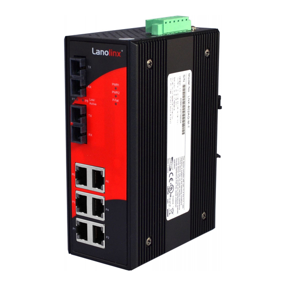
Front Panel The Front Panel of the 6 10/100/1000TX +2G fiber industrial switch is shown as below: Front Panel of the industrial switch Top View The top panel of the 6 10/100/1000TX + 2G fiber industrial switch has one terminal block connector of two DC power inputs. -
Page 9: Led Indicators
LED Indicators There are diagnostic LED indicators located on the front panel of the industrial switch. They provide real-time information of system and optional status. The following table provides description of the LED status and their meanings for the switch. Status Description Per Unit... -
Page 10: Green Ethernet
100Mbps Green Ethernet The 6 10/100/1000TX + 2G fiber industrial switch has a special function. The switch will automatically detect Ethernet ports status and Cable Length and adjust power efficiency. Below table shows 6 10/100/1000TX + 2G fiber industrial switch power consumption. Link Up: Cable Length 20m Green power (off/on) Consumption (Watts) -
Page 11: Hardware Installation
Hardware Installation In this paragraph, we will describe how to install the 6 10/100/1000TX + 2G fiber industrial switch and the installation points to be attended to it. Installation Steps 1. Unpack the Industrial switch 2. Check if the DIN-Rail is screwed on the Industrial switch or not. If the DIN-Rail is not screwed on the Industrial switch, please refer to DIN-Rail Mounting section for DIN- Rail installation. -
Page 12: Wiring The Power Inputs
less than 100 meters (328 ft.) long. Fiber segment using single-mode connector type must use 9/125µm single-mode fiber cable. User can connect two devices in the distance up to 10 Kilometers. Fiber segment using multi-mode connector type must use 50/125 or 62.5/125 µm multi-mode fiber cable. -
Page 13: Wiring The P-Fail Alarm Contact
Wiring the P-Fail Alarm Contact The P-Fail alarm contact is in the middle of terminal block connector as the picture shows below. Inserting the wires, will detect the P-Fail status including power failure or port link failure (managed industrial switch only) and from a Normally Close circuit. Please refer to the diagrams below for the P-Fail alarm contact, and the application example for the P-Fail alarm operation. - Page 14 First, insert the top of DIN-Rail into the track. Then, lightly push the DIN-Rail into the track.
-
Page 15: Wall Mount Plate Mounting
Check if the DIN-Rail is tightened on the track or not. To remove the industrial switch from the track, reverse steps above. Wall Mount Plate Mounting Follow the steps as below to mount the industrial switch with wall mount plate. Remove the DIN-Rail from the industrial switch;... - Page 16 Use screws to screw the wall mount plate on the rear side...
-
Page 17: Network Application
Network Application This chapter provides some sample applications to help user to have more actual idea of industrial switch function application. A sample application of the industrial switch is shown as below. -
Page 18: Troubles Shooting
Troubles shooting Verify that is using the right power cord/adapter (DC 12-48V), please don’t use the power adapter with DC output higher than 48V, or it will burn this converter down. Select the proper UTP cable to construct user network. Please check that is using the right cable.
Need help?
Do you have a question about the LNX-802AG-S10-T and is the answer not in the manual?
Questions and answers