Table of Contents
Advertisement
Quick Links
Product User Manual
and enterprise branch and head offices LNX-501AG-SFP-T
www.enochsystems.com
1-877-722-1116
sales@enochsystems.com
Copyright © 2013 Enoch Systems, LLC, Enoch Systems and the Enoch Systems logo are trademarks or registered trademarks of Enoch Systems, LLC and/or its affiliates in the U.S. and other countries.
Third-party trademarks mentioned are the property of their respective owners. All rights reserved.
Advertisement
Table of Contents

Related Manuals for ANTAIRA LNX-501AG-SFP-T


Summary of Contents for ANTAIRA LNX-501AG-SFP-T
- Page 1 Product User Manual and enterprise branch and head offices LNX-501AG-SFP-T www.enochsystems.com 1-877-722-1116 sales@enochsystems.com Copyright © 2013 Enoch Systems, LLC, Enoch Systems and the Enoch Systems logo are trademarks or registered trademarks of Enoch Systems, LLC and/or its affiliates in the U.S. and other countries.
- Page 2 4-port 10/100/1000T + 1 SFP Industrial Ethernet Switch User Manual...
- Page 3 Content Overview ............1 Introduction .............. 1 Features ..............4 Packing List .............. 5 Safety Precaution ............. 5 Hardware Description ......... 6 Front Panel ............... 6 Top View ..............7 Wiring the Power Inputs ........... 7 Wiring the Fault Alarm Contact ........ 8 LED Indicators ............
- Page 4 Installation Steps ............ 19 Troubles shooting ..........21 Technical Specification ........22...
-
Page 5: Overview
Overview Introduction Aside from 4 x 10/100/1000Base-TX fast Ethernet ports, the industrial switch comes equipped with 1 SFP (mini-GBIC) port. Traditional RJ-45 ports can be used for uplinking wide-band paths in short distance (< 100 m), while the SFP slots can be used for the application of wideband uploading and long distance transmissions to fit the field request flexibility. - Page 6 Dual Power Input 4 10/100/1000T + 1 SFP Industrial Switch’s redundant power input design is with power reserve protection to prevent the switch device broken by wrong power wiring. When one of power input is fail, P-Fail LED will turn on and send an alarm through a relay output for notifying user.
- Page 7 Easy Troubleshooting indicators make troubleshooting quick easy. Each 10/100/1000 Base-TX port has 2 LEDs that display the link status and transmission speed. Also the three power indicators P1, P2 and Fault help you diagnose immediately.
-
Page 8: Features
Features Provides 4 x 10/100/1000Base-T Mbps Ethernet ports Provides 1 x SFP (mini-GBIC) port Supports full/half duplex flow control Supports auto-negotiation Supports MDI/MDI-X auto-crossover Supports MAC Address up to 8Kbytes Supports Jumbo Frame of 9Kbytes ... -
Page 9: Packing List
Packing List 1 x 4 10/100/1000T + 1 SFP Industrial Switch 1 x User Manual 2 x Wall Mounting Bracket and Screws Safety Precaution Attention IF DC voltage is supplied by an external circuit, please use a protection device on the power supply input. -
Page 10: Hardware Description
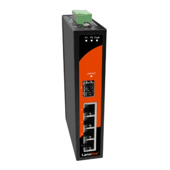
Hardware Description In this paragraph, we will introduce the Industrial switch’s hardware spec, port, cabling information, and wiring installation. Front Panel The Front Panel of the 4 10/100/1000T + 1 SFP Industrial Switch is shown as below. Front Panel of the 4 10/100/1000T + 1 SFP Industrial Switch... -
Page 11: Top View
Top View The top panel of the 4 10/100/1000T + 1 SFP Industrial Switch is equipped one terminal block connector of two DC power inputs. Top panel of the 4 10/100/1000T + 1 SFP Industrial Switch Wiring the Power Inputs Please follow the steps below to insert the power wire. -
Page 12: Wiring The Fault Alarm Contact
Wiring the Fault Alarm Contact The fault alarm contact is in the middle of terminal block connector as the picture shows below. Inserting the wires, it will detect the fault status which the power is failure or port link failure (for managed model) and form an open circuit. -
Page 13: Led Indicators
LED Indicators There are few LEDs display the power status and network status located on the front panel of the Industrial switch, each of them has its own specific meaning as below table. Color Description Power input 1 is active Green Power input 1 is inactive Power input 2 is active... - Page 14 Note “+” and “-” signs represent the polarity of the wires that make up each wire pair. All ports on this industrial switch support automatic MDI/MDI-X operation, you can use straight-through cables (See Figure below) for all network connections to PCs or servers, or to other switches or hubs. In straight-through cable, pins 1, 2, 3, and 6, at one end of the cable, are connected straight through to pins 1, 2, 3 and 6 at the other end of the cable.
- Page 15 Straight through cables schematic Cross over cables schematic...
-
Page 16: Cabling
Cabling Use the four twisted-pair, Category 5e or above cabling for RJ-45 port connection. The cable between the switch and the link partner (switch, hub, workstation, etc.) must be less than 100 meters (328 ft.) long. As for the small form-factor pluggable (SFP) is a compact optical transceiver used in optical communications for both telecommunication and data communication applications. - Page 17 Figure 2.9: Transceiver Inserted...
- Page 18 Second, insert the fiber cable of LC connector into the transceiver. Figure 2.10: LC connector to the transceiver To remove the LC connector from the transceiver, please follow the steps shown below: First, press the upper side of the LC connector from the transceiver and pull it out to release.
- Page 19 Second, push down the metal loop and pull the transceiver out by the plastic part. Figure 2.12: Pull out from the SFP module...
-
Page 20: Mounting Installation
Mounting Installation DIN-Rail Mounting The DIN-Rail is screwed on the industrial switch when out of factory. If the DIN-Rail is not screwed on the industrial switch, please see the following pictures to screw the DIN-Rail on the switch. Follow the steps below to hang the industrial switch. - Page 21 After the DIN-Rail is screwed on the rear side of the switch, insert the top of DIN-Rail into the track. Then, lightly push the DIN-Rail into the track. Check if the DIN-Rail is tightened on the track or not. To remove the industrial switch from the track, reverse steps above.
-
Page 22: Wall Mount Plate Mounting
Wall Mount Plate Mounting Follow the steps below to mount the industrial switch with wall mount plate. Remove the DIN-Rail from the industrial switch; loose the screws to remove the DIN-Rail. Place the wall mount plate on the rear panel of the industrial switch. Use the screws to screw the wall mount plate on the industrial switch. -
Page 23: Hardware Installation
Hardware Installation In this paragraph, we will describe how to install the 5-port 10/100/1000Base-TX Industrial Switch and the installation points for the attention. Installation Steps Unpacked the Industrial switch. Check the DIN-Rail is screwed on the Industrial switch. If the DIN-Rail is not screwed on the Industrial switch. - Page 24 Power on the Industrial switch. How to wire the power; please refer to the Wiring the Power Inputs section. The power LED on the Industrial switch will light up. Please refer to the LED Indicators section for meaning of LED lights. Prepare the twisted-pair, straight through Category 5e/above cable for Ethernet connection and SFP transceiver with LC cable for fiber connection.
-
Page 25: Troubleshooting
Troubleshooting Verify that you are using the right power cord/adapter (DC 12 ~ 48V), please don’t use the power adapter with DC output higher than 48V, or it will burn this switch down. Select the proper UTP cable to construct your network. Please check that you are using the right cable. -
Page 26: Technical Specification
Technical Specification The technical specifications of the Industrial Switch are listed as follows. Communications IEEE 802.3, 802.3u, 802.3ab Compatibility IEEE 802.3x, 802.3z 10/100/1000Base-T, 1000Base-FX Transmission Speed Up to 1000 Mbps Interface Connectors 4 x RJ-45 (4-port 10/100/1000TX) 6-pin removable screw terminal (power &... - Page 27 Enclosure IP-30, Metal shell with solid mounting kits Mounting DIN35 rail, Wall Protection ESD (Ethernet) 4,000 V Surge (EFT for power) 3,000 V Power Reverse Overload current protection Environment Operating Temperature -40 ~ 75 (wide operating temp. model) C (standard model) -10 ~ 60 5% ~ 95% (non-condensing) Operating Humidity...
- Page 28 CE EN61000-6-2 CE EN61000-6-4 Free Fall IEC60068-2-32 Shock IEC60068-2-27 Vibration IEC60068-2-6...
Need help?
Do you have a question about the LNX-501AG-SFP-T and is the answer not in the manual?
Questions and answers