
Subscribe to Our Youtube Channel
Related Manuals for ANTAIRA LNP-1204GN-T


Summary of Contents for ANTAIRA LNP-1204GN-T
- Page 1 LNP-1204GN-T User’s Manual 12-port Managed Gigabit Industrial Ethernet Switch with 8 x Gigabit Combo Ports and 4 x 1000BaseX SFP Ports User’s Manual Version 1.2 Antaira Technologies...
-
Page 2: Copyright Notice
Antaira warrants that all Antaira products are free from defects in material and workmanship for a specified warranty period from the invoice date (5 years for most products). Antaira will repair or replace products found by Antaira to be defective within this warranty period, with shipment expenses apportioned by Antaira and the distributor. -
Page 3: Table Of Contents
LNP-1204GN-T User’s Manual Table of Contents Getting to Know Your Switch ................ 6 About the LNP-1204GN-T Industrial Switch............. 6 Software Features ....................6 Hardware Features ....................7 Hardware Installation ..................8 Installation Switch on DIN-Rail ................. 8 2.1.1 Mount Series on DIN-Rail ..................8 Wall Mounting Installation .................. - Page 4 LNP-1204GN-T User’s Manual 5.1.3.1 Setting ...................... 31 5.1.3.2 DHCP Dynamic Client List ..............32 5.1.3.3 DHCP Client List ..................32 5.1.4 Port Setting ......................33 5.1.4.1 Port Control ..................... 33 5.1.4.2 Rate Limit ....................34 5.1.4.3 Port Trunk ....................35 5.1.4.4...
- Page 5 LNP-1204GN-T User’s Manual 5.1.12 Monitor and Diagnostics ................86 5.1.12.1 MAC Table ....................86 5.1.12.2 Port Statistic .................... 88 5.1.12.2.1 Traffic Overview ................... 88 5.1.12.2.2 Detailed Statistics ................89 5.1.12.3 Port Mirroring ..................91 5.1.12.4 System Log ....................92 5.1.12.5 Cable Diagonstics ...................
-
Page 6: Getting To Know Your Switch
Know Your Switch 1.1 About the LNP-1204GN-T Industrial Switch The LNP-1204GN-T is powerful full Gigabit managed industrial switch which have many features. The switch can work under wide temperature, dusty environment and humid condition. They can be managed by Windows Utility, WEB, TELNET and Console or other third-party SNMP software as well. -
Page 7: Hardware Features
LNP-1204GN-T User’s Manual 1.3 Hardware Features Dual DC power inputs for power redundancy Operating Temperature: -40 to 70 Storage Temperature: -40 to 85 Operating Humidity: 5% to 95%, non-condensing Casing: IP-30 8 x 10/100/1000Base –T(X) ... -
Page 8: Hardware Installation
LNP-1204GN-T User’s Manual ardware Installation 2.1 Installation Switch on DIN-Rail Each switch has a Din-Rail kit on rear panel. The Din-Rail kit helps switch to fix on the Din-Rail. It is easy to install the switch on the Din-Rail: 2.1.1 Mount Series on DIN-Rail Step 1: Slant the switch and mount the metal spring to Din-Rail. -
Page 9: Wall Mounting Installation
LNP-1204GN-T User’s Manual Step 2: Push the switch toward the Din-Rail until you heard a “click” sound. 2.2 Wall Mounting Installation Each switch has another installation method for users to fix the switch. A wall mount panel can be found in the package. The following steps show how to mount the switch on... -
Page 10: Mount Lnp-1204Gn-T On Wall
LNP-1204GN-T User’s Manual 2.2.1 Mount LNP-1204GN-T on wall Step 1: Remove Din-Rail kit. Step 2: Use 6 screws that can be found in the package to combine the wall mount panel. Just like the picture shows below: Antaira Technologies... - Page 11 LNP-1204GN-T User’s Manual The screws specification shows in the following two pictures. In order to prevent switches from any damage, the screws should not larger than the size that used in LNP-1204GN-T switch. Pozidrive Antaira Technologies...
-
Page 12: Hardware Overview
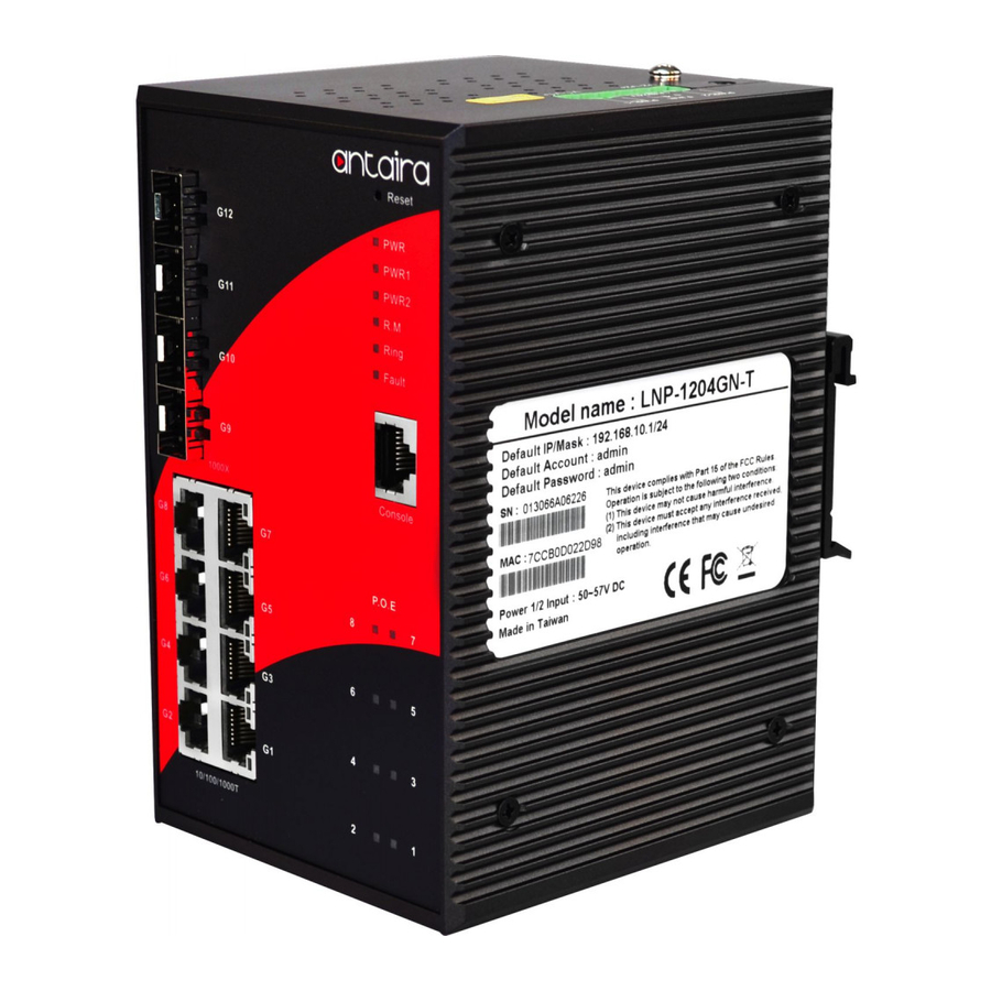
LNP-1204GN-T User’s Manual ardware Overview 3.1 Front Panel The following table describes the labels that stick on the LNP-1204GN-T Port Description 4 1000BaseX on SFP port SFP ports 8 10/100/1000Base-T(X) P.S.E. RJ45 Port Use RS-232 with RJ-45 connecter to manage switch. -
Page 13: Front Panel Leds
LNP-1204GN-T User’s Manual 9. P.O.E LED 10. LED for Ethernet ports link status. 11. 10/100/1000Base-T(X) ports 12. 1000 Base-X SFP ports 13. LED for SFP ports link status. 3.2 Front Panel LEDs Color Status Description Green DC power module up Green DC power module 1activated. -
Page 14: Top View Panel
LNP-1204GN-T User’s Manual 3.3 Top View Panel The bottom panel component of LNP-1204GN-T is showed as below: 1. Terminal block includes: PWR1, PWR2 (50-57V DC) 2. Ground wired Antaira Technologies... -
Page 15: Rear Panel
LNP-1204GN-T User’s Manual 3.4 Rear Panel The rear panel components of LNP-1204GN-T are showed as below: 1. Screw holes for wall mount kit. 2. Din-Rail kit Antaira Technologies... -
Page 16: Cables
4.1 Ethernet Cables The LNP-1204GN-T switch has standard Ethernet ports. According to the link type, the switch use CAT 3, 4, 5,5e UTP cables to connect to any other network device (PCs, servers, switches, routers, or hubs). Please refer to the following table for cable specifications. - Page 17 BI_DB- BI_DD+ BI_DD- The LNP-1204GN-T switch supports auto MDI/MDI-X operation function. You can use a straight-through cable to connect PC to switch. The following table below shows the 10BASE-T/ 100BASE-TX MDI and MDI-X port pin outs. 10/100 Base-T MDI/MDI-X pins assignment...
-
Page 18: Sfp
Fiber cord 4.3 Console Cable LNP-1204GN-T switch can be management by console port. The DB-9 to RJ-45 cable can be found in the package. You can connect them to PC via a RS-232 cable with DB-9 female connector and the other end (RJ-45 connector) connects to console port of switch. -
Page 19: Web Management
LNP-1204GN-T User’s Manual EB Management 5.1 Configuration by Web Browser This section introduces the configuration by Web browser. 5.1.1 About Web-based Management An embedded HTML web site resides in flash memory on the CPU board. It contains advanced management features and allows you to manage the switch from anywhere on the network through a standard web browser such as Microsoft Internet Explorer. - Page 20 LNP-1204GN-T User’s Manual The login screen appears. Key in the username and password. The default username and password is “admin”. Click “Enter” or ”OK” button, then the main interface of the Web-based management appears. Login screen Main Interface Main interface...
-
Page 21: Basic Setting
LNP-1204GN-T User’s Manual 5.1.2 Basic Setting System Information 5.1.2.1 The switch system information is provided here. System Information interface Label Description The textual identification of the contact person for this managed node, together with information on how to contact this person. -
Page 22: Admin & Password
LNP-1204GN-T User’s Manual Click to undo any changes made locally and revert to previously saved values. Admin & Password 5.1.2.2 This page allows you to configure the system password required to access the web pages or log in from CLI. -
Page 23: Ip Setting
LNP-1204GN-T User’s Manual IP Setting 5.1.2.3 Configure the switch-managed IP information on this page. Label Description Enable the DHCP client by checking this box. If DHCP fails and DHCP Client the configured IP address is zero, DHCP will retry. If DHCP fails and the configured IP address is non-zero, DHCP will stop and the configured IP settings will be used. -
Page 24: Https
LNP-1204GN-T User’s Manual Click to save changes. Click to undo any changes made locally and revert to previously saved values. Click to renew DHCP. This button is only available if DHCP is enabled. HTTPS 5.1.2.4 Label Description Indicates the HTTPS mode operation. Possible modes are: Mode Enabled: Enable HTTPS mode operation. -
Page 25: Ssh
LNP-1204GN-T User’s Manual 5.1.2.5 Label Description Indicates the SSH mode operation. Possible modes are: Enabled: Enable SSH mode operation. Mode Disabled: Disable SSH mode operation. Click to save changes. Click to undo any changes made locally and revert to previously saved values. - Page 26 LNP-1204GN-T User’s Manual seconds. Each LLDP frame contains information about how long the information in the LLDP frame shall be considered valid. The Tx Hold LLDP information valid period is set to Tx Hold multiplied by Tx Interval seconds. Valid values are restricted to 2 - 10 times.
- Page 27 LNP-1204GN-T User’s Manual discarded (Unrecognized CDP TLVs and discarded CDP frame are not shown in the LLDP statistic. Only). CDP TLVs are mapped into LLDP neighbors table as shown below. CDP TLV "Device ID" is mapped into the LLDP "Chassis ID" field.
- Page 28 LNP-1204GN-T User’s Manual LLDP Neighbor Information This page provides a status overview for all LLDP neighbors. The displayed table contains a row for each port on which an LLDP neighbor is detected. The columns hold the following information: Label Description The port on which the LLDP frame was received.
- Page 29 LNP-1204GN-T User’s Manual Click to refresh the page immediately. Check this box to enable an automatic refresh of the page at regular intervals. LLDP Statistics This page provides an overview of all LLDP traffic. Two types of counters are shown. Global counters are counters that refer to the whole stack, switch, while local counters refer to counters for the currently selected switch.
-
Page 30: Backup/Restore Configuration
LNP-1204GN-T User’s Manual error. If an LLDP frame is received on a port, and the switch's internal table has run full, the LLDP frame is counted and discarded. This situation is known as "Too Many Neighbors" in the LLDP standard. LLDP frames require a new entry in the table when the... -
Page 31: Firmware Update
LNP-1204GN-T User’s Manual Firmware Update 5.1.2.8 This page facilitates an update of the firmware controlling the stack. switch. 5.1.3 DHCP Server 5.1.3.1 Setting The system provides with DHCP server function. Enable the DHCP server function, the switch system will be a DHCP server. -
Page 32: Dhcp Dynamic Client List
LNP-1204GN-T User’s Manual 5.1.3.2 DHCP Dynamic Client List When the DHCP server function is activated, the system will collect the DHCP client information and display in here. 5.1.3.3 DHCP Client List You can assign the specific IP address which is in the assigned dynamic IP range to the specific port. -
Page 33: Port Setting
LNP-1204GN-T User’s Manual 5.1.4 Port Setting 5.1.4.1 Port Control This page displays current port configurations. Ports can also be configured here. Label Description Port This is the logical port number for this row. The current link state is displayed graphically. Green indicates the Link link is up and red that it is down. -
Page 34: Rate Limit
LNP-1204GN-T User’s Manual The Usage column shows the current percentage of the power consumption per port. The Configured column allows for changing the power savings mode parameters per port. Power Control Disabled: All power savings mechanisms disabled. ActiPHY: Link down power savings enabled. -
Page 35: Port Trunk
LNP-1204GN-T User’s Manual "kbps", and it is restricted to 1-1000 when the "Policer Unit" is "Mbps" Configure the unit of measure for the port policer rate as kbps or Policer Unit Mbps. The default value is "kbps". Shaper Enabled Enable or disable the port shaper. The default value is "Disabled". - Page 36 LNP-1204GN-T User’s Manual the frame. Check to enable the use of the IP Address, or uncheck to disable. By default, IP Address is enabled. TCP/UDP Port The TCP/UDP port number can be used to calculate the Number destination port for the frame. Check to enable the use of the TCP/UDP Port Number, or uncheck to disable.
-
Page 37: Lacp Port Configuration
LNP-1204GN-T User’s Manual 5.1.4.3.2 LACP Port Configuration This page allows the user to inspect the current LACP port configurations, and possibly change them as well. Label Description Port Indicates the group ID for the settings contained in the same row. -
Page 38: Lacp System Status
LNP-1204GN-T User’s Manual Click to save changes. Click to undo any changes made locally and revert to previously saved values. 5.1.4.3.3 LACP System Status This page provides a status overview for all LACP instances. Label Description Aggr ID The Aggregation ID associated with this aggregation instance. For... -
Page 39: Lacp Status
LNP-1204GN-T User’s Manual 5.1.4.3.4 LACP Status This page provides a status overview for LACP status for all ports. Label Description Port The switch port number. LACP 'Yes' means that LACP is enabled and the port link is up. 'No' means that LACP is not enabled or that the port link is down. -
Page 40: Lacp Statistics
LNP-1204GN-T User’s Manual The Aggregation ID assigned to this aggregation group. Aggr ID Partner System ID The partners System ID (MAC address). Partner Port The partners port number connected to this port. Click to refresh the page immediately. Check this box to enable an automatic refresh of the page at regular intervals. -
Page 41: Port Trunk
LNP-1204GN-T User’s Manual Label Description Port The switch port number LACP Transmitted Shows how many LACP frames have been sent from each port LACP Received Shows how many LACP frames have been received at each port. Discarded Shows how many unknown or illegal LACP frames have been discarded at each port. -
Page 42: Redundancy
LNP-1204GN-T User’s Manual Locked:This port has been locked to avoid looping. Click to save changes. Click to undo any changes made locally and revert to previously saved values. 5.1.5 Redundancy 5.1.5.1 Ring The recovery time of Ring is less than 20 ms. It can reduce unexpected damage caused by network topology change. -
Page 43: Mstp
LNP-1204GN-T User’s Manual The primary port, when this switch is Ring Master. Ring Port The backup port, when this switch is Ring Master. Ring Port Mark to enable Coupling Ring. Coupling Ring can be used to Coupling Ring divide a big ring into two smaller rings to avoid effecting all switches when network topology change. -
Page 44: Msti Mapping
LNP-1204GN-T User’s Manual The maximum age of the information transmitted by the Bridge when it is the Root Bridge. Valid values are in the range 6 to 40 Max Age seconds, and MaxAge must be <= (FwdDelay-1)*2. This defines the initial value of remainingHops for MSTI information generated at the boundary of an MSTI region. -
Page 45: Msti Priorities
LNP-1204GN-T User’s Manual Label Description The name identifiying the VLAN to MSTI mapping. Bridges must share the name and revision (see below), as well as the Configuration Name VLAN-to-MSTI mapping configuration in order to share spanning trees for MSTI's. (Intra-region). The name is at most 32 characters. -
Page 46: Cist Ports
LNP-1204GN-T User’s Manual Label Description The bridge instance. The CIST is the default instance, which is MSTI always active. Controls the bridge priority. Lower numerical values have better priority. The bridge priority plus the MSTI instance number, Priority concatenated with the 6-byte MAC address of the switch forms a Bridge Identifier. - Page 47 LNP-1204GN-T User’s Manual ports are chosen as forwarding ports in favor of higher path cost ports. Valid values are in the range 1 to 200000000. Controls the port priority. This can be used to control priority of Priority ports having identical port cost. (See above).
-
Page 48: Msti Ports
LNP-1204GN-T User’s Manual Click to save changes. Click to undo any changes made locally and revert to previously saved values. MSTI Ports This page allows the user to inspect the current STP MSTI port configurations, and possibly change them as well. A MSTI port is a virtual port, which is instantiated seperately for each active CIST (physical) port for each MSTI instance configured and applicable for the port. - Page 49 LNP-1204GN-T User’s Manual Label Description The switch port number of the corresponding STP CIST (and Port MSTI) port. Controls the path cost incurred by the port. The Auto setting will set the path cost as appropriate by the physical link speed, using the 802.1D recommended values.
-
Page 50: Stp Port Status
LNP-1204GN-T User’s Manual Label Description The Bridge Instance. This is also a link to the STP Detailed Bridge MSTI Status. Bridge ID The Bridge ID of this Bridge instance. Root ID The Bridge ID of the currently elected root bridge. - Page 51 LNP-1204GN-T User’s Manual Label Description Port The switch port number of the logical STP port. The current STP port role of the CIST port. The port role can be CIST Role one of the following values: AlternatePort BackupPort RootPort DesignatedPort.
-
Page 52: Vlan
LNP-1204GN-T User’s Manual STP Statistics This page displays the RSTP port statistics counters for bridge ports in the currently selected switch. Label Description Port The switch port number of the logical RSTP port. The number of RSTP Configuration BPDU's received/transmitted RSTP on the port. - Page 53 LNP-1204GN-T User’s Manual Label Description Delete Check to delete the entry. It will be deleted during the next save. The VLAN ID for the entry. VLAN ID MAC Address The MAC address for the entry. Checkmarks indicate which ports are members of the entry.
- Page 54 LNP-1204GN-T User’s Manual Example: Portbased VLAN Setting (For ingress port) 1. VLAN Membership Configuration setting port 1 & VID=50 2. VLAN Port 1 Configuration-->Disable VLAN Aware 3. VLAN Port 1 Configuration-->Mode=specific,ID=50 Antaira Technologies...
- Page 55 LNP-1204GN-T User’s Manual (For egress port) 1. VLAN Membership Configuration setting port 2 & VID=50 2. VLAN Port 2 Configuration-->don't care VLAN Aware 3. VLAN Port 2 Configuration-->Mode=specific,ID=50 (any packet can enter egress port ) Antaira Technologies...
- Page 56 LNP-1204GN-T User’s Manual 802.1Q Access port Setting (For ingress port) 1. VLAN Membership Configuration setting port & VID=50 2. VLAN Port Configuration-->Enable VLAN Aware 3. VLAN Port Configuration-->Mode=specific,ID=50 Antaira Technologies...
- Page 57 LNP-1204GN-T User’s Manual (For egress port) 1. VLAN Membership Configuration setting port & VID=50 2. VLAN Port Configuration-->Disable VLAN Aware 3. VLAN Port Configuration-->Mode=specific,ID=50 (untagged & tag=50 packet can enter egress port ) Antaira Technologies...
- Page 58 LNP-1204GN-T User’s Manual 802.1Q Trunk port setting (multi-tag) (For ingress port) 1. VLAN Membership Configuration setting port & VID=11,22,33 2. VLAN Port Configuration-->Enable VLAN Aware Antaira Technologies...
- Page 59 LNP-1204GN-T User’s Manual 3. VLAN Port Configuration-->Mode=specific,ID=11 (when enterring packet is untagged frame, added tag = 11 When entering the tagged frame, only VID = 11,22,33 three kinds of packets can pass) (For egress port) 1. VLAN Membership Configuration setting port, VID=11,22,33...
- Page 60 LNP-1204GN-T User’s Manual 2. VLAN Port Configuration-->Enable VLAN Aware 3. VLAN Port Configuration-->Mode=none (egress port can receive tag=11,22,33 packet In addition ,ony tag=11packet can enter egress port ) Antaira Technologies...
- Page 61 LNP-1204GN-T User’s Manual Q-in-Q VLAN Setting ingress Port 1------------------->egress Port 2 (For ingress port-----Port 1) 1. VLAN Membership Configuration setting port 1、2、3 & VID=50 2. VLAN Port Configuration-->Disable Port 1 VLAN Aware Antaira Technologies...
- Page 62 LNP-1204GN-T User’s Manual 3. VLAN Port Configuration-->Port 1 Mode=specific,ID=50 (For egress port ----Port 2) 1. VLAN Membership Configuration setting port & VID=50 Antaira Technologies...
- Page 63 LNP-1204GN-T User’s Manual 2. VLAN Port Configuration-->Enable Port 2、3 VLAN Aware. 3. VLAN Port Configuration-->Mode=none (only tag=50 packet can enter egress port ) Antaira Technologies...
-
Page 64: Private Vlan
LNP-1204GN-T User’s Manual 5.1.6.2 Private VLAN The Private VLAN membership configurations for the switch can be monitored and modified here. Private VLANs can be added or deleted here. Port members of each Private VLAN can be added or removed here. Private VLANs are based on the source port mask, and there are no connections to VLANs. -
Page 65: Snmp
LNP-1204GN-T User’s Manual Label Description A check box is provided for each port of a private VLAN. When checked, port isolation is enabled for that port. Port Members When unchecked, port isolation is disabled for that port. By default, port isolation is disabled for all ports. - Page 66 LNP-1204GN-T User’s Manual USM for authentication and privacy and the community string will associated with SNMPv3 communities table Indicates the community write access string to permit access to SNMP agent. The allowed string length is 0 to 255, and the allowed content is the ASCII characters from 33 to 126.
- Page 67 LNP-1204GN-T User’s Manual Indicates the SNMP trap destination address. Trap Destination Trap Destination IPv6 Address Address Provide the trap destination IPv6 address of this switch. IPv6 address is in 128-bit records represented as eight fields of up to four hexadecimal digits with a colon separates each field (:). For example, Trap Destination 'fe80:215:c5ff:fe03:4dc7'.
-
Page 68: Snmp-Communities
LNP-1204GN-T User’s Manual Indicates the SNMP trap security engine ID. SNMPv3 sends traps and informs using USM for authentication and privacy. A unique engine ID for these traps and informs is needed. When "Trap Probe Trap Security Security Engine ID" is enabled, the ID will be probed automatically. -
Page 69: Snmp-Users
LNP-1204GN-T User’s Manual 5.1.7.3 SNMP-Users Configure SNMPv3 users table on this page. The entry index keys are Engine ID and User Name. Label Description Check to delete the entry. It will be deleted during the next save. Delete An octet string identifying the engine ID that this entry should belong to. -
Page 70: Snmp-Groups
LNP-1204GN-T User’s Manual MD5: An optional flag to indicate that this user using MD5 authentication protocol. SHA: An optional flag to indicate that this user using SHA authentication protocol. The value of security level cannot be modified if entry already exists. -
Page 71: Snmp-Views
LNP-1204GN-T User’s Manual security models are: v1: Reserved for SNMPv1. v2c: Reserved for SNMPv2c. usm: User-based Security Model (USM). A string identifying the security name that this entry should belong to. Security Name The allowed string length is 1 to 32, and the allowed content is the ASCII characters from 33 to 126. -
Page 72: Snmp-Accesses
LNP-1204GN-T User’s Manual another view entry which view type is 'included' and it's OID subtree overstep the 'excluded' view entry. The OID defining the root of the subtree to add to the named view. OID Subtree The allowed OID length is 1 to 128. The allowed string content is digital number or asterisk(*). -
Page 73: Traffic Prioritization
LNP-1204GN-T User’s Manual request may potentially SET new values. The allowed string length is 1 to 32, and the allowed content is the ASCII characters from 33 to 126. 5.1.8 Traffic Prioritization 5.1.8.1 Port Configuration This page allows you to configure QoS settings for each port. -
Page 74: Qos Control List
LNP-1204GN-T User’s Manual Configure the default QoS class for the port, that is, the QoS class Default Class for frames not matching any of the QCEs in the QCL. QCL# Select which QCL to use for the port. Select the default tag priority for this port when adding a Tag to Tag Priority the untagged frames. - Page 75 LNP-1204GN-T User’s Manual Label Description Select a QCL to display a table that lists all the QCEs for that QCL# particular QCL. Specifies which frame field the QCE processes to determine the QoS class of the frame. The following QCE types are supported: Ethernet Type: The Ethernet Type field.
-
Page 76: Storm Control
LNP-1204GN-T User’s Manual 5.1.8.3 Storm Control Storm control for the switch is configured on this page. There is a unicast storm rate control, multicast storm rate control, and a broadcast storm rate control. These only affect flooded frames, i.e. frames with a (VLAN ID, DMAC) pair not present on the MAC Address table. -
Page 77: Wizard
LNP-1204GN-T User’s Manual 5.1.8.4 Wizard This handy wizard helps you set up a QCL quickly. Label Description Set up Group ports into several types according to different QCL policies. Port Policies Set up Typical Set up the specific QCL for different typical network application Network quality control. -
Page 78: Igmp Snooping
LNP-1204GN-T User’s Manual 5.1.9 IGMP Snooping 5.1.9.1 IGMP Snooping This page provides IGMP Snooping related configuration. Label Description Snooping Enabled Enable the Global IGMP Snooping. Unregistered IPMC Flooding Enable unregistered IPMC traffic flooding. enabled VLAN ID The VLAN ID of the entry. -
Page 79: Igmp Snooping Status
LNP-1204GN-T User’s Manual If an aggregation member port is selected as a router port, the whole aggregation will act as a router port. Fast Leave Enable the fast leave on the port. 5.1.9.2 IGMP Snooping Status Label Description VLAN ID The VLAN ID of the entry. -
Page 80: Security
LNP-1204GN-T User’s Manual 5.1.10 Security 5.1.10.1 ACL Configure the ACL parameters (ACE) of each switch port. These parameters will affect frames received on a port unless the frame matches a specific ACE. Label Description Port The logical port for the settings contained in the same row. - Page 81 LNP-1204GN-T User’s Manual Specify the port shut down operation of this port. The allowed values are: Shutdown Enabled: If a frame is received on the port, the port will be disabled. Disabled: Port shut down is disabled. The default value is "Disabled".
-
Page 82: Client Configuration
LNP-1204GN-T User’s Manual Client Configuration The table has one row for each Client and a number of columns, which are: Label Description Client The Client for which the configuration below applies. Authentication Method can be set to one of the following values:... - Page 83 LNP-1204GN-T User’s Manual Common Server Configuration These setting are common for all of the Authentication Servers. Label Description The Timeout, which can be set to a number between 3 and 3600 seconds, is the maximum time to wait for a reply from a server.
-
Page 84: Warning
LNP-1204GN-T User’s Manual Port The UDP port to use on the RADIUS Authentication Server. If the port is set to 0 (zero), the default port (1812) is used on the RADIUS Authentication Server. The secret - up to 29 characters long - shared between the Secret RADIUS Accounting Server and the switchstack. -
Page 85: System Warning
LNP-1204GN-T User’s Manual 5.1.11.2 System Warning 5.1.11.2.1 Syslog Setting The SYSLOG is a protocol to transmit event notification messages across networks. Please refer to RFC 3164 - The BSD SYSLOG Protocol The following table describes the labels in this screen. -
Page 86: Monitor And Diagnostics
LNP-1204GN-T User’s Manual Label Description Alert when system restart. System Start Alert when a power up or down. Power Status SNMP Authentication Alert when SNMP authentication failure Failure Redundant Ring Alert when Ring topology change. Topology Change Alert when Link Up, Link Down, or Link Up & Link Down. - Page 87 LNP-1204GN-T User’s Manual Aging Configuration By default, dynamic entries are removed from the MAC after 300 seconds. This removal is also called aging. Configure aging time by entering a value here in seconds; for example, Age time seconds. The allowed range is 10 to 1000000 seconds.
-
Page 88: Port Statistic
LNP-1204GN-T User’s Manual Static MAC Table Configuration The static entries in the MAC table are shown in this table. The static MAC table can contain 64 entries. The maximum of 64 entries is for the whole stack, and not per switch. -
Page 89: Detailed Statistics
LNP-1204GN-T User’s Manual Label Description Port The logical port for the settings contained in the same row. The number of received and transmitted packets per port. Packets Bytes The number of received and transmitted bytes per port. The number of frames received in error and the number of Errors incomplete transmissions per port. - Page 90 LNP-1204GN-T User’s Manual Detailed Statistics-Receive & Transmit Total Label Description Rx and Tx Packets The number of received and transmitted (good and bad) packets. The number of received and transmitted (good and bad) bytes. Rx and Tx Octets Includes FCS, but excludes framing bits.
-
Page 91: Port Mirroring
LNP-1204GN-T User’s Manual The number of frames dropped due to excessive or late collisions. Tx Late / Exc.Coll. Short frames are frames that are smaller than 64 bytes. Long frames are frames that are longer than the configured maximum frame length for this port. -
Page 92: System Log
LNP-1204GN-T User’s Manual port. Frames received are not mirrored. Disabled : Neither frames transmitted nor frames received are mirrored. Enabled : Frames received and frames transmitted are mirrored to the mirror port. Note: For a given port, a frame is only transmitted once. It is therefore not possible to mirror Tx frames for the mirror port. - Page 93 LNP-1204GN-T User’s Manual Error: Error level of the system log. All: All levels. Time The time of the system log entry. Message The MAC Address of this switch. Check this box to enable an automatic refresh of the page at regular intervals.
-
Page 94: Cable Diagonstics
LNP-1204GN-T User’s Manual 5.1.12.5 Cable Diagonstics This page is used for running the VeriPHY Cable Diagnostics. Press to run the diagnostics. This will take approximately 5 seconds. If all ports are selected, this can take approximately 15 seconds. When completed, the page refreshes automatically, and you can view the cable diagnostics results in the cable status table. -
Page 95: Ping
LNP-1204GN-T User’s Manual Label Description Port The port where you are requesting VeriPHY Cable Diagnostics. Cable Status Port: Port number. Pair: The status of the cable pair. Length: The length (in meters) of the cable pair. 5.1.12.6 Ping This page allows you to issue ICMP PING packets to troubleshoot IP connectivity issues. -
Page 96: Power Over Ethernet (P.o.e.)
LNP-1204GN-T User’s Manual 5.1.13 Power over Ethernet (P.O.E.) 5.1.13.1 PoE Configuration - Reserved Power determined There are three modes for configuring how the ports/PDs may reserve power. Label Description Allocated mode In this mode the user allocates the amount of power that each port may reserve. -
Page 97: Poe Configuration - Power Management Mode
LNP-1204GN-T User’s Manual 5.1.13.2 PoE Configuration - Power management Mode There are 2 modes for configuring when to the ports are shut down. Label Description Actual Consumption In this mode the ports are shut down when the actual power consumption for all ports exceeds the amount of power that the power supply can deliver or if the actual power consumption for a given port exceeds the reserved power for that port. -
Page 98: Poe Configuration - Port Configuration
LNP-1204GN-T User’s Manual 5.1.13.4 PoE Configuration - Port Configuration User can configuration every port PoE Setting Antaira Technologies... -
Page 99: Power Over Ethernet Status
LNP-1204GN-T User’s Manual Label Description PoE Enable The PoE Enabled represents whether the PoE is enable for the port. Priority The Priority represents the ports priority. There are three levels of power priority named Low, High and Critical. The priority is used in the case where the remote devices requires uses more power than power supply can deliver. -
Page 100: Lldp Power Over Ethernet Neighbor
LNP-1204GN-T User’s Manual 5.1.13.6 LLDP Power Over Ethernet Neighbor This page provides a status overview for all LLDP PoE neighbors. The displayed table contains a row for each port on which an LLDP PoE neighbor is detected. The columns hold the following information:... -
Page 101: System Reboot
LNP-1204GN-T User’s Manual The Power Value contains a numerical value that indicates the Maximum Power maximum power in watts required by a PD device from a PSE device, or the minimum power a PSE device is capable of sourcing over a maximum length cable based on its current configuration. -
Page 102: Factory Defaults
LNP-1204GN-T User’s Manual Factory Defaults You can reset the configuration of the stack switch on this page. Only the IP configuration is retained. Label Description Click to reset the configuration to Factory Defaults. Click to return to the Port State page without resetting the... -
Page 103: Command Line Interface Management
LNP-1204GN-T User’s Manual ommand Line Interface Management About CLI Management Besides WEB-based management, LNP-1204GN-T also supports CLI management. You can use console or telnet to management switch by CLI. CLI Management by RS-232 Serial Console (115200, 8, none, 1, none) Before Configuring by RS-232 serial console, use an RJ45 to DB9-F cable to connect the Switches’... - Page 104 LNP-1204GN-T User’s Manual Step 2. Input a name for new connection Step 3. Select to use COM port number Antaira Technologies...
- Page 105 LNP-1204GN-T User’s Manual Step 4. The COM port properties setting, 115200 for Bits per second, 8 for Data bits, None for Parity, 1 for Stop bits and none for Flow control. Step 5. The Console login screen will appear. Use the keyboard to enter the Username and Password (The same with the password for Web Browser), then press “Enter”.
- Page 106 LNP-1204GN-T User’s Manual CLI Management by Telnet Users can use “TELNET” to configure the switches. The default value is as below: IP Address: 192.168.10.1 Subnet Mask: 255.255.255.0 Default Gateway: 192.168.10.254 User Name: admin Password: admin Follow the steps below to access the console via Telnet.
- Page 107 LNP-1204GN-T User’s Manual Commander Groups System Configuration [all] [<port_list>] Reboot Restore Default [keep_ip] Contact [<contact>] Name [<name>] Location [<location>] System> Description [<description>] Password <password> Username [<username>] Timezone [<offset>] Log [<log_id>] [all|info|warning|error] [clear] Syslog Syslog> ServerConfiguration [<ip_addr>] Antaira Technologies...
- Page 108 LNP-1204GN-T User’s Manual Configuration DHCP [enable|disable] IP> Setup [<ip_addr>] [<ip_mask>] [<ip_router>] [<vid>] Ping <ip_addr_string> [<ping_length>] SNTP [<ip_addr_string>] Auth Configuration Timeout [<timeout>] Deadtime [<dead_time>] RADIUS [<server_index>] [enable|disable] [<ip_addr_string>] [<secret>] [<server_port>] Auth> ACCT_RADIUS [<server_index>] [enable|disable] [<ip_addr_string>] [<secret>] [<server_port>] Client [console|telnet|ssh|web] [none|local|radius] [enable|disable] Statistics [<server_index>]...
- Page 109 LNP-1204GN-T User’s Manual Aggr Configuration Add <port_list> [<aggr_id>] Delete <aggr_id> Aggr> Lookup [<aggr_id>] Mode [smac|dmac|ip|port] [enable|disable] LACP Configuration [<port_list>] Mode [<port_list>] [enable|disable] Key [<port_list>] [<key>] LACP> Role [<port_list>] [active|passive] Status [<port_list>] Statistics [<port_list>] [clear] Configuration Version [<stp_version>] Non-certified release, v Txhold [<holdcount>]lt 15:15:15, Dec 6 2007...
- Page 110 LNP-1204GN-T User’s Manual Port RestrictedRole [<port_list>] [enable|disable] Port RestrictedTcn [<port_list>] [enable|disable] Port bpduGuard [<port_list>] [enable|disable] Port Statistics [<port_list>] Port Mcheck [<port_list>] Msti Port Configuration [<msti>] [<port_list>] Msti Port Cost [<msti>] [<port_list>] [<path_cost>] Msti Port Priority [<msti>] [<port_list>] [<priority>] Dot1x Configuration [<port_list>] Mode [enable|disable] State [<port_list>] [macbased|auto|authorized|unauthorized]...
- Page 111 LNP-1204GN-T User’s Manual LLDP Configuration [<port_list>] Mode [<port_list>] [enable|disable|rx|tx] Optional_TLV [<port_list>][port_descr|sys_name|sys_descr|sys_capa|mgmt_addr] [enable|disable] Interval [<interval>] LLDP> Hold [<hold>] Delay [<delay>] Reinit [<reinit>] Info [<port_list>] Statistics [<port_list>] [clear] Configuration [<port_list>] Add <mac_addr> <port_list> [<vid>] Delete <mac_addr> [<vid>] Lookup <mac_addr> [<vid>] MAC> Agetime [<age_time>] Learning [<port_list>] [auto|disable|secure]...
- Page 112 LNP-1204GN-T User’s Manual PVLAN Configuration [<port_list>] Add <pvlan_id> [<port_list>] PVLAN> Delete <pvlan_id> Lookup [<pvlan_id>] Isolate [<port_list>] [enable|disable] Configuration [<port_list>] Classes [<class>] Default [<port_list>] [<class>] Tagprio [<port_list>] [<tag_prio>] QCL Port [<port_list>] [<qcl_id>] QCL Add [<qcl_id>] [<qce_id>] [<qce_id_next>] (etype <etype>) | (vid <vid>) | (port <udp_tcp_port>) |...
- Page 113 LNP-1204GN-T User’s Manual Configuration [<port_list>] Action [<port_list>] [permit|deny] [<rate_limiter>] [<port_copy>] [<logging>] [<shutdown>] Policy [<port_list>] [<policy>] Rate [<rate_limiter_list>] [<packet_rate>] Add [<ace_id>] [<ace_id_next>] [switch | (port <port>) | (policy <policy>)] [<vid>] [<tag_prio>] [<dmac_type>] [(etype [<etype>] [<smac>] [<dmac>]) | ACL> (arp [<sip>] [<dip>] [<smac>] [<arp_opcode>] [<arp_flags>]) | [<sip>] [<dip>] [<protocol>] [<ip_flags>]) |...
- Page 114 LNP-1204GN-T User’s Manual Community Lookup [<index>] User Add <engineid> <user_name> [MD5|SHA] [<auth_password>] [DES] [<priv_password>] User Delete <index> User Changekey <engineid> <user_name> <auth_password> [<priv_password>] User Lookup [<index>] Group Add <security_model> <security_name> <group_name> Group Delete <index> Group Lookup [<index>] View Add <view_name> [included|excluded] <oid_subtree>...
-
Page 115: T Echnical Specifications
LNP-1204GN-T User’s Manual echnical Specifications LNP-1204GN-T Switch Model Physical Ports Ggiabit Combo Port with 10/100/1000Base-T(X) and 1000Base-X SFP Port Technology IEEE 802.3 for 10Base-T, IEEE 802.3u for 100Base-T(X) IEEE 802.3z for 1000Base-X IEEE 802.3ab for 1000Base-T, IEEE 802.3x for Flow control IEEE 802.3ad for LACP (Link Aggregation Control Protocol ) - Page 116 LNP-1204GN-T User’s Manual 10/100/1000Base-T(X) RJ45 port Green for port Link/Act. indicator PoE indicator Green for PoE enable indicator 1000Base-X Fiber port indicator Green for port Link/Act. Fault contact Relay Relay output to carry capacity of 1A at 24VDC Power Redundant Input power Dual DC inputs.
Need help?
Do you have a question about the LNP-1204GN-T and is the answer not in the manual?
Questions and answers