
Related Manuals for ANTAIRA LNX-1802G


Summary of Contents for ANTAIRA LNX-1802G
- Page 1 16-port 10/100TX + 2-Port 10/100/1000T Mini-GBIC Combo Industrial Ethernet Switch User Manual...
- Page 2 FCC Warning This E quipment has been t ested and found to comply with the limits for a Class-A digital device, pur suant t o P art 15 o f the F CC r ules. These lim its are designed to provide reasonable protection against harmful interference in a r esidential i nstallation.
-
Page 3: Table Of Contents
Content Introduction ..............1 Features ..............1 Package Contents ............ 2 Hardware Description ..........3 Physical Dimension ..........3 Front Panel .............. 3 Top View ..............4 LED Indicators ............4 Ports ................. 6 Cabling ..............8 Wiring the Power Inputs ......... 12 Wiring the Fault Alarm Contact ...... -
Page 4: Introduction
Introduction The 16 10 /100TX + 2 1 0/100/1000T/Mini-GBIC Co mbo I ndustrial S witch is a cost- effective s olution and meets the high r eliability r equirements demanded by i ndustrial applications. Using fiber por t c an ex tend t he c onnection distance t hat i ncreases the network elasticity and performance. -
Page 5: Package Contents
Package Contents Please refer to the package content list below to verify them against the checklist. 16 10/100TX + 2 10/100/1000T/Mini-GBIC Combo Industrial Switch Pluggable Terminal Block User manual 2 wall mount plates with screws One DIN-Rail (attached on the switch) ... -
Page 6: Hardware Description
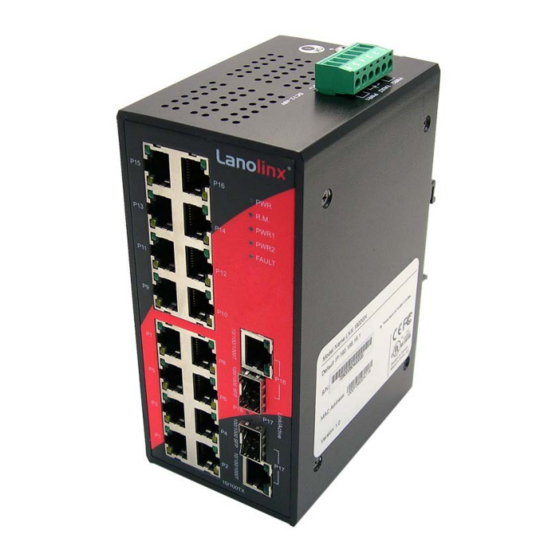
Hardware Description In this paragraph, it will describe the Industrials witch’s hardware spec, port, cabling information, and wiring installation. Physical Dimension 16 10/100TX + 2 10/100/1000T/Mini-GBIC Combo Industrial Switch dimension (W x D x H) is 72mm x 105mm x 152mm Front Panel The front panel of the 16 10/100TX + 2 10/100/1000T/Mini-GBIC C ombo I ndustrial Switch is shown as below:... -
Page 7: Top View
Top View The top panel of the 16 10/100TX + 2 10/100/1000T/Mini-GBIC Combo Industrial Switch has one terminal block connector of two DC power inputs. Top Panel of the industrial switch LED Indicators The diagnostic LEDs located on the front panel of the industrial switch provide real-time information of system and optional status. - Page 8 PWR1 & PWR2 are both active or no power inputs Green Connected to network (Upper LED) Blinking Networking is active (Upper LED) Not connected to network (Upper LED) P1 ~ P16 Yellow Ethernet port full duplex (Lower LED) Blinking Collision of packets occurs (Lower LED) Ethernet port half duplex or not connected to (Lower LED)
-
Page 9: Ports
Ports RJ-45 ports The UTP/STP ports will a uto-sense f or 10Base-T/100Base-TX connections (Fast Ethernet) or 10Base-T, 100Base-TX, o r 10 00Base-T connections (Gigabit E thernet). Auto M DI/MDIX m eans th at the sw itch can c onnect t o another switch or w orkstation without changing straight through or crossover cabling. - Page 10 Straight Through Cable Schematic Cross Over Cable Schematic 2 Gigabit Copper/SFP (Mini-GBIC) combo port: The I ndustrial s witch has t wo a uto-detected Giga po rt—UTP/STP/Fiber combo por ts. The G igabit C opper ( 10/100/1000T) p orts s hould us e C ategory 5e or ab ove U TP/STP cable f or the connection up t o 10 00Mbps.
-
Page 11: Cabling
Cabling Twisted-pair s egment c an be es tablished by us ing unshielded t wisted pai r ( UTP) or shielded t wisted pair (STP) c abling. T he c able be tween t he l ink partner ( switch, hub , workstation, e tc.) and t he c onverter must b e l ess t han 100 meters ( 328 ft.) l ong and comply with the IEEE 802.3ab 1000Base-T standard for Category 5e or above. - Page 12 Make sure the module is aligned correctly and then slide the module into the S FP slot until a click is heard. Figure 2.9: Transceiver Inserted...
- Page 13 Second, insert the fiber cable of LC connector into the transceiver. Figure 2.10: LC connector to the transceiver To remove the LC connector from the transceiver, please follow the steps shown below: First, pr ess t he u pper s ide o f t he LC c onnector from t he t ransceiver and p ull i t ou t t o release.
- Page 14 Second, push down the metal loop and pull the transceiver out by the plastic part. Figure 2.12: Pull out from the SFP module...
-
Page 15: Wiring The Power Inputs
Wiring the Power Inputs Please follow the steps below to insert the power wire. 1. Insert the positive and negative wires into the V+ and V- contacts on the terminal block connector. 2. To tighten the wire-clamp screws for preventing the DC wires to loose. -
Page 16: Wiring The Fault Alarm Contact
Wiring the Fault Alarm Contact The fault alarm contact is in the middle of terminal block connector as the picture shows below. Inserting the wires, it will detect the fault status which the power is failure or port link failure (for managed model) and form an open circuit. Insert the wires into the fault alarm contact (No. -
Page 17: Mounting Installation
Mounting Installation DIN-Rail Mounting The D IN-Rail is screwed on the industrial switch when out of factory. If the DIN-Rail is not screwed on the industrial switch, please see the following pictures to screw the DIN- Rail on the switch. Follow the steps below to hang the industrial switch. - Page 18 First, insert the top of DIN-Rail into the track. Then, lightly push the DIN-Rail into the track. Check if the DIN-Rail is tightened on the track or not. To remove the industrial switch from the track, reverse steps above.
-
Page 19: Wall Mount Plate Mounting
Wall Mount Plate Mounting Follow the steps below to mount the industrial switch with wall mount plate. 1. Remove the DIN-Rail from the industrial switch; loose the screws to remove the DIN- Rail. 2. Place the wall mount plate on the rear panel of the industrial switch. 3. -
Page 20: Hardware Installation
Hardware Installation In th is paragraph, we will des cribe how t o i nstall t he 16 10 /100TX + 2 10/100/1000T/Mini-GBIC C ombo I ndustrial S witch and t he i nstallation p oints to be attended to it. Installation Steps 1. -
Page 21: Network Application
Network Application This chapter provides some sample applications to help user to have more actual idea of industrial s witch f unction ap plication. A s ample ap plication of t he i ndustrial s witch i s shown as below:... -
Page 22: Troubles Shooting
Troubles shooting Verify t hat you are using t he r ight pow er c ord/adapter ( DC 12-48V). Please don’t use the power adapter with DC output higher than 48V, or this switch will be burned down. Select t he pr oper U TP/STP c able t o c onstruct the user n etwork. Use uns hielded ... -
Page 23: Technical Specification
Technical Specification The 16 1 0/100TX + 2 1 0/100/1000T/Mini-GBIC Co mbo I ndustrial S witch technical specification are as follows. IEEE 802.3 10Base-T IEEE 802.3u 100Base-TX IEEE 802.3ab 1000Base-T Standard IEEE 802.3z Gigabit fiber IEEE 802.3x Flow Control and Back-pressure CSMA/CD Protocol 14,880 pps for 10Base-T Ethernet port... - Page 24 LC (Multi-mode): 50/125um or 62.5/125um Optical cable LC (Single mode): 9/125um 7.2Gbps Back-plane Packet throughput 10.7Mpps at 64bytes ability 12 ~ 48 V Redundant power with polarity reverse protection and removable terminal block Power Supply (The power supply should meet the “document listed by UL”...
- Page 25 CE EN61000-4-12 CE EN61000-6-2 CE EN61000-6-4 Safety UL 60950-1 IEC60068-2-32 (Free fall) IEC60068-2-27 (Shock) Stability testing IEC60068-2-6 (Vibration)
Need help?
Do you have a question about the LNX-1802G and is the answer not in the manual?
Questions and answers