
Subscribe to Our Youtube Channel
Related Manuals for ANTAIRA LNX-800AG


Summary of Contents for ANTAIRA LNX-800AG
-
Page 1: User Manual
LNX-800AG 8-Port Industrial Gigabit Unmanaged Ethernet Switches - w/8*10/100/1000Tx User Manual... -
Page 2: Fcc Warning
FCC Warning This equipment has been tested and found to comply with the limits for a Class-A digital device, pursuant to Part 15 of the FCC rules. These limits are designed to provide reasonable protection against harmful interference in a residential installation. This equipment generates, uses, and can radiate radio frequency energy. -
Page 3: Table Of Contents
Table of Contents Introduction ..............1 Features ..............1 Package Contents ............ 2 Hardware Description ..........3 Physical Dimension ..........3 Front Panel .............. 4 Top View ..............4 LED Indicators ............5 Ports ................. 5 Cabling ..............7 Wiring the Power Inputs ........... 7 Wiring the Fault Alarm Contact ........ -
Page 4: Introduction
This assures that data is properly transmitted. The LNX-800AG switch supports 12~48VDC dual power inputs, and also offers an extended operating temperature model (w/-T) that can withstand -40°C ~ 75°C. It supports IEEE 802.3/802.3u/802.3x/802.3ab with 10/100/1000BTx for full or half duplex data transmission. -
Page 5: Package Contents
Provides EFT Protection 3,000 VDC for Power Line Supports 6,000 VDC Ethernet ESD Protection Package Contents Please refer to the package contents list below. LNX-800AG - 8-Port Industrial Gigabit Unmanaged Switch with DIN Rail Bracket User Manual Removable Terminal Block ... -
Page 6: Hardware Description
Hardware Description The Industrial switch’s hardware spec, port, cabling information, and wiring installation will be described below. Physical Dimension The LNX-500AG - 5-Port Industrial Gigabit Unmanaged Ethernet Switch Dimensions: (W x D x H) 30mm x 95mm x 140mm... -
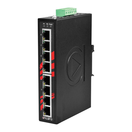
Page 7: Front Panel
Front Panel The front panel of the Industrial switch is shown below: Front Panel of the Industrial Switch Top View The top view of the Industrial switch has one terminal block connector of two DC power inputs and relay circuit contact. Top View of the Industrial Switch... -
Page 8: Led Indicators
LED Indicators The diagnostic LEDs located on the front panel of the Industrial switch provide real-time information of the system and optional status. The following table provides the description of the LED status. Color Description Power input 1 is active Green Power input 1 is inactive Power input 2 is active... - Page 9 All ports on this Industrial switch support an automatic MDI/MDI-X operation, and users can use straight-through cables (see figure below) for all network connections to PCs or servers, or to other switches or hubs. With straight-through cable, pins 1, 2, 3, and 6, at one end of the cable, are connected straight through to pins 1, 2, 3 and 6 at the other end of the cable.
-
Page 10: Cabling
The following figure shows the 10/100/1000 Ethernet RJ-45 pin outs. Cabling Use unshielded twisted-pair (UTP) or shielded twisted-pair (STP) cable for RJ-45 connections: 100Ω Category 3, 4 or 5 cable for 10Mbps connections, 100Ω Category 5 cable for 100Mbps, or 100Ω Category 5e/above cable for 1000Mbps connections. ... -
Page 11: Wiring The Fault Alarm Contact
2. Tighten the wire-clamp screws to prevent the wires from loosening. The wire gauge for the terminal block should be in the range Note between 12~ 24 AWG. If only using one power source, jumper Pin 1 to Pin 5 and Pin 2 to Pin 6 to eliminate power fault alarm. -
Page 12: Mounting Installation
Mounting Installation DIN-Rail Mounting The DIN-Rail is screwed on the Industrial switch from the factory. If the DIN-Rail is not screwed on the Industrial switch, please see the following pictures to screw the DIN-Rail on the switch. Follow the steps below to hang the Industrial switch. Use the screws to screw the DIN-Rail bracket on the rear side of the Industrial switch. - Page 13 After the DIN-Rail bracket is screwed on the rear side of the switch, insert the top of DIN-Rail on to the track. Then, lightly pull down the bracket on to the rail. Check if the bracket is mounted tight on the rail. To remove the Industrial switch from the rail, reverse steps above.
-
Page 14: Wall Mounting
Wall Mounting Follow the steps below to mount the Industrial switch using the wall mount bracket. 1. Remove the DIN-Rail bracket from the Industrial switch; loosen the screws to remove the DIN-Rail. 2. Place the wall mount bracket on the top and bottom of the Industrial switch. 3. -
Page 15: Hardware Installation
Hardware Installation This section is to explain how to install the LNX-500AG – 5-Port Industrial Gigabit Unmanaged Ethernet Switch. Installation Steps 1. Unpack the Industrial switch packing. 2. Check if the DIN-Rail bracket is screwed on the Industrial switch. If the DIN-Rail is not screwed on the Industrial switch, please refer to the DIN-Rail Mounting section for DIN-Rail installation. -
Page 16: Network Application
Network Application This segment provides an example of an Industrial switch application. -
Page 17: Troubleshooting
If the power indicator LED does not turn on when the power cord is plugged in, the user may have a problem with the power cord. Check for loose power connections, power losses or surges at the power outlet. Please contact Antaira or Antaira’s authorized channel partners for technical support service, if the problem still cannot be resolved. -
Page 18: Technical Specification
Technical Specification The LNX-800AG - 8-Port Industrial Gigabit Unmanaged Ethernet Switch technical specifications are shown below. IEEE 802.3 10Base-T Ethernet IEEE 802.3u 100Base-TX Fast Ethernet Standard IEEE 802.3ab 1000Base-Tx Gigabit Ethernet IEEE802.3x Flow Control and Back Pressure Protocol CSMA/CD 14,880pps for 10Base-T Ethernet port... - Page 19 Installation DIN Rail Mounting, Wall Mounting Standard Operating Temperature: -10 C to 70 Operating Temp. Extend Operating Temperature: -40 C to 75 Operating Humidity 5% to 95% (Non-Condensing) Storage Temperature C to 85 Case Dimension IP-30, 30mm (W) x 95mm (D) x 140mm (H) FCC Class A CE EN61000-4-2/3/4/5/6/8 CE EN61000-6-2...
Need help?
Do you have a question about the LNX-800AG and is the answer not in the manual?
Questions and answers