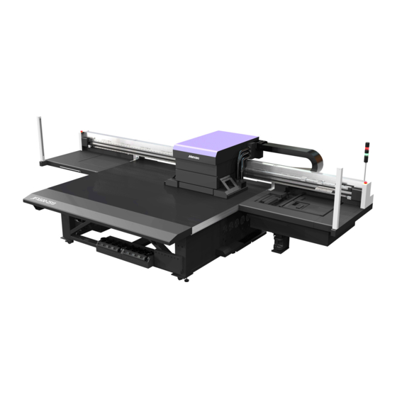
MIMAKI JFX550-2513 Operation Manual
Uv inkjet printer
Hide thumbs
Also See for JFX550-2513:
- Operation manual (164 pages) ,
- Care and maintenance (28 pages) ,
- Manual (20 pages)

Subscribe to Our Youtube Channel
Related Manuals for MIMAKI JFX550-2513


Summary of Contents for MIMAKI JFX550-2513
- Page 1 You can also download the latest manual from official website. MIMAKI ENGINEERING CO., LTD. https://mimaki.com/ D203593-10 Original instructions...
-
Page 2: Table Of Contents
TABLE OF CONTENTS Introduction .................. 5 To ensure safe use ................. 7 Symbols .................... 7 Usage Precautions ................ 8 Usage Restrictions................ 13 Hazardous and Prohibited Actions ............. 14 Ink or any Other Liquid Used with the Machine ...... 17 Ink Specifications................ 18 Restrictions concerning the product ........... - Page 3 Repositioning the UV-LED Unit ............ 66 Starting Printing .................. 67 Stopping Printing ................ 69 Moving the Y-Bar ................ 69 Chapter 3 Settings (MPC) 3.1 Mimaki Printer Controller ............ 72 Screen Structure................. 72 3.2 Print menu ................ 76 3.3 Maintenance menu .............. 77 Nozzle Checking................. 79 3.4 Setting 1 Menu................
- Page 4 Chapter 5 Dealing with Problems 5.1 Troubleshooting .............. 108 The power does not turn on.............. 108 Printing is not possible.............. 108 The media jams or the media is dirty.......... 108 Image defects occur................. 108 A pressure error occurred.............. 111 The ink has leaked................
-
Page 5: Introduction
Adobe, the Adobe logo, Acrobat, Illustrator, Photoshop, and PostScript are the trademarks or registered trademarks of Adobe Incorporated in the United States and other countries. RasterLink is a trademark or a registered trademark of Mimaki Engineering Co. Ltd. in Japan and other countries. - Page 6 Introduction l Voluntary restraint of electromagnetic interference Use of this product at home may cause jamming. Such incidents may require the user to take appropriate measures.
-
Page 7: To Ensure Safe Use
To ensure safe use To ensure safe use Symbols In this manual, the symbols indicate and explain precautions. Make sure you fully understand the meaning of each symbol and use the machine safely and correctly. Explanation WARNING Indicates a potential hazard that may result in death or serious injury if handled improperly or if instructions are disregarded. -
Page 8: Usage Precautions
To ensure safe use Usage Precautions l In the event of abnormal conditions • In the event of abnormal conditions such as smoke or unusual odor, turn off the main power immediately and unplug the power cable. Continuing to use the product under these conditions may result in failure, electric shock, or fire. - Page 9 ±10%/24A, Ground 50/60±1Hz • For power connectionsfrom the 21 series, perform all required electrical work between the switchboard and terminal block. All electrical work must be performed by a licensed electrician. For more information, please contact a Mimaki service representative.
- Page 10 To ensure safe use • Do not turn off the main power supply for the machine or control PC. Turning off the power supply will disable the automatic maintenance function (including nozzle clogging prevention and ink discharge channel cleaning functions). This will increase the risk of print defects (e.g., nozzle clogging, deflection).
- Page 11 To ensure safe use • Long hair should be tied back. Failure to do so may result in injury. l Do not disassemble or repair • Do not attempt to disassemble or repair this machine. Otherwise there is a risk of failure, electric shock, or fire.
- Page 12 To ensure safe use • Do not press, rub, or push the touch panel with excessive force. • Do not touch the touch panel with a ball-point pen or other hard metal object. • Do not touch the black frame of the screen. •...
-
Page 13: Usage Restrictions
To ensure safe use Usage Restrictions • This machine poses significant safety hazards due to the high-speed movement of the carriage from side to side, Y-bar movements, sections with high temperatures and hazardous voltages, and the UV-LED. Use of the machine is restricted to operators with a thorough understanding of the hazards involved. -
Page 14: Hazardous And Prohibited Actions
To ensure safe use Hazardous and Prohibited Actions When the power is on, avoid any of the following hazardous actions: Serious injury (crushing or shearing) may result if the carriage moves, as during routine maintenance. l Maintain a safe distance from the area behind the Y-bar. •... - Page 15 To ensure safe use l Keep your face, hands, and all other body parts at a safe distance from moving parts. • Do not move your face, hands, or any other body parts close to or into the gap between the Y- bar and belt.
- Page 16 To ensure safe use l Keep your eyes averted from the UV-LED. • Avoid looking directly at the UV-LED. The carriage is roughly at eye level when you are seated. Take special care if you work while seated. l Maintain a safe distance while the carriage is operating. •...
-
Page 17: Ink Or Any Other Liquid Used With The Machine
Leaking ink may adhere to the skin or get into the eyes or mouth. • Use only dedicated Mimaki Engineering anti freezing liquid. Use of other anti freezing liquid may cause failures or reduce print quality. -
Page 18: Ink Specifications
Storage in such places increases the risk of failure or printing defects (e.g., nozzle clogging, deflection). Ink Specifications Item Details Type UV curing ink (MIMAKI product) Color Cyan (C) Magenta (M) Yellow (Y) Black (K) White (W) -
Page 19: Restrictions Concerning The Product
Ink or any Other Liquid Used with the Machine Item Details • Where possible, avoid storing in cold locations below 0 °C and hot locations above 40 °C. • Ink quality may deteriorate if stored outside these conditions. Restrictions concerning the product The ink expiration date is indicated on the Ink bottle. -
Page 20: Installation Precautions
Installation Precautions Installation Precautions • Do not install this machine in environments where flammable substances are present (e.g., gasoline, flammable spray, alcohol, thinner, lacquer, or powder). This machine is not explosion- proof. The product poses a risk of explosion. • Do not install this machine in locations where open flames are present. The ink may ignite. •... -
Page 21: Installation Space
Installation Precautions Installation Space Provide the following space around the machine to allow safe and proper replacement of ink and media: Item JFX600-2513 JFX550-2513 At least 7,270 mm (5,270 mm) Width At least 4,800 mm (2,800 mm) Depth (1,600 mm) -
Page 22: Adjuster Feet
Installation Precautions Adjuster Feet Before turning the machine on, make sure the adjuster feet are secured firmly. If any adjuster foot is loose, the machine may move during printing, resulting in injuries. • Do not remove the floor plate (made of resin, color: gray). The floor plate helps distribute the weight of the machine. -
Page 23: Warning Label
Warning Label Warning Label Make sure you fully understand the details indicated on the various warning labels. If any of the warning labels becomes dirty and illegible or peel off, contact your local dealer or our service office to request new warning labels. - Page 24 Warning Label Order code Label M909381 M903330 M906115 M902663 M905980 M917293 (JFX600) M917294 (JFX550) M909385 M903281 M907935...
-
Page 25: Chapter 1 Before Use
Chapter 1 Before Use This chapter This chapter describes information essential before use, such as part names. Part Names and Functions ......26 System Configuration ........3 1 Carriage ............. 28 Control PC ........... 3 1 Capping station .......... 28 Connecting to a Local Network ....3 1 Ink status lamp ........... -
Page 26: Part Names And Functions
Chapter 1 Before Use 1.1 Part Names and Functions Name Summary Y-bar The Y-bar is equipped with a carriage. This part moves over the table to print. Table Print area. Features a large number of holes used to secure the media under vacuum pressure. - Page 27 "Replacing Ink"(P. 37) 13 Touch panel The touch panel is used to control the machine. "Mimaki Printer Controller"(P. 72) • How to operate the touch panel – Tap: Select the function. – Long tap (long press): Select the multiple jobs.
-
Page 28: Carriage
Chapter 1 Before Use Carriage The carriage incorporates print heads that discharge ink, a UV-LED lamp for curing UV ink, and a jam sensor that stops the carriage in case of media jamming. Printing occurs as ink is ejected while traversing left and right. -
Page 29: Signal Tower (Indicator Light)
Chapter 1 Before Use Color Status Summary No error Green Illuminated Ink is being supplied (no error) Flashing One of the following errors has occurred: Printing is possible. • INK NEAR END • Ink expired (1 month passed) Illuminated One of the following errors has occurred: Printing is not possible. •... -
Page 30: Light Curtain
Chapter 1 Before Use Light curtain Detection of a person or object will halt the machine. : Detection area : Area not detected (86.5 mm above the table surface) • Objects 86.5 mm from the table surface cannot be detected. Parts of the body or other objects in this area cannot be detected. -
Page 31: System Configuration
Generates RIP data. Printing with the touch panel Control PC The machine is controlled using the MPC (Mimaki Printer Controller) application installed on the control PC. "Settings (MPC)"(P. 71) The control PC is connected to the machine with a LAN cable. - Page 32 Chapter 1 Before Use l Method 1 for checking the LAN connection of the control PC From MENU on the touch panel, touch [SETTING 2] > [System setting] > [Network setting]. • A dialog box appears. Touch the [Manual] radio button. •...
-
Page 33: Preparing The Rip Computer
The explanation here applies to MIMAKI RIP software (RasterLink). Launch “Profile Update”. (1) From the Start menu, select [Mimaki RasterLink7] > [Profile Update]. (2) Click [Next]. Select the JFX550-2513, JFX600-2513 being used. - Page 34 • “Profile Update” closes. • For more information, refer to the RasterLink installation guide. https://mimaki.com/download/ software.html • Download the latest color profiles from the Mimaki website. The profiles downloaded can be installed using Profile Manager. https://mimaki.com/download/inkjet.html [JFX550-2513, JFX600-2513] > [Profile] Setting Up RIP Software The explanation here applies to MIMAKI RIP software (RasterLink).
- Page 35 Chapter 1 Before Use Register JFX550-2513, JFX600-2513. (1) Click [Add]. (2) Set the specifics for JFX550-2513, JFX600-2513. • Model: Select the model. • Color: Select the ink set filled. • Output port: Select the file. • Available Printers: Select JFX550-2513, JFX600-2513 connected.
-
Page 36: Ink Replacement Method
Chapter 1 Before Use 1.3 Ink Replacement Method When Ink Near End is Displayed Ink levels are low. We recommend replacing with new Ink bottle as soon as possible. Note that ink may run out during printing. You can check which Ink bottle must be replaced in INK STATUS on touch panel. "INK STATUS"(P. -
Page 37: Replacing Ink
Chapter 1 Before Use Ink type Cap type • LUS210 ink [Cap B] • Primer ink Replacing Ink l Removing the Ink bottle Rotate the lever on the tank section from left to right. • Never turn the ink bottle. Doing so may result in leaking ink. Lift the ink bottles vertically. - Page 38 Chapter 1 Before Use • The O-ring fitted to the special cap may become detached when removing an ink bottle. Refit the O-ring if it becomes detached. Soak up any ink droplets on the special caps. • Use a wipe filter to soak up ink droplets and prevent dripping. Wipe filter Wipe off any ink on the special caps with paper wipes.
- Page 39 Chapter 1 Before Use l Preparing the Ink bottle Shake the Ink bottle to the left and right slowly at least 20 times. • Tighten the ink bottle lid securely, then shake the bottle slowly from left to right to ensure that the ink moves inside, holding the ink bottle lid with a paper towel.
- Page 40 Chapter 1 Before Use • Wipe off any ink or maintenance liquid remaining on the ink bottle or special cap. Otherwise there is a risk of ink leakage due to the special cap spinning freely. • Check to confirm that there is no foreign matter, such as paper towel scraps or dust, adhering to the special cap.
- Page 41 Chapter 1 Before Use l Mounting the Ink bottle The order of Ink bottle to be set depends on the ink set you are currently using. Check the ink slot numbers, then insert the correct color Ink bottle. Ink set Ink layout 4-color, W, Cl 4-color, W, Cl, Pr...
- Page 42 Chapter 1 Before Use Insert a new ink IC chip into the slot on the ink supply unit. • Insert the ink IC chip with the metal side facing up. Inserting it in the wrong way may cause failure of the machine or damage the ink IC chip. •...
-
Page 43: Chapter 2 Printing
Chapter 2 Printing This chapter This chapter describes printing procedures and settings. Print Process ...........44 Test Printing ............. 5 6 Checking Print Head Discharge....5 6 Load the media..........46 Checking White Ink Discharge..... 5 7 Media ............46 Printing Defects..........5 8 Load the media. -
Page 44: Print Process
Chapter 2 Printing 2.1 Print Process Setting Up RIP Software "Installing the Mimaki Driver"(P. 33) (required first time only) "Installing RIP Software"(P. 33) (required first time only) "Obtaining Color Profiles"(P. 33) "Setting Up RIP Software"(P. 34) (required first time only) Set up the control PC and RIP computer on the same local network. - Page 45 Chapter 2 Printing "Test Printing"(P. 56) Good example Bad example Deflection Nozzle clogging Clean the head to clear malfunctioning nozzles. "Head Cleaning"(P. 59) Adjust the drop position for bi-directional printing. "Correcting the Drop Position"(P. 61) In this case, the drop position correction value is -4.0 Import the RIP data (jobs) in MPC.
-
Page 46: Load The Media
Media l Media handling precautions • Use Mimaki-approved media to ensure consistent high-quality printing. • Protect media from dust when stored. Otherwise print quality may be reduced. • When storing standard-size media rolled up, store with the coated surface facing out. -
Page 47: Load The Media
Chapter 2 Printing Load the media. Supported Media Thickness 0.0 mm to 60.0 mm (default value 0.0 mm) • Be careful to avoid dropping heavy media on the table. Disregarding this precaution may impair the precision of the board surface and affect print quality. Load the media on the table. -
Page 48: Setting The Media Origin
Chapter 2 Printing Positioning Pin The guide holes on the table surface will let you load media straight to the table. Attach the included positioning pin to adjust the position at which media is loaded. Rear side [Table] 5 mm For commercially available screws 200 mm [Print Area]... - Page 49 Chapter 2 Printing Touch [Start]. • The carriage moves to the specified media origin, and the JOG operation screen is activated. Move the LED pointer to the preferred position. • You can change the origin by entering a value.
- Page 50 Chapter 2 Printing Touch [Set] after the screen indicates the measured value. Touch [End]. Touch [X] in the upper right to close the dialog box. Entering a Value to Set the Origin From MENU on the touch panel, tap [SETTING 2]. Touch [Media] >...
- Page 51 Chapter 2 Printing • Use the [Numeric keypad] to enter your specified value. (1) Touch • A dialog box appears. [Enter] (2) Enter the preferred value, then touch [Enter]. Touch [Set].
-
Page 52: Registering The Media Thickness
Chapter 2 Printing 2.3 Registering the Media Thickness Set media thickness as follows: Item Automatically register media thickness. "Measuring Automatically"(P. 52) Manually register media thickness. "Entering Values Manually"(P. 53) Measuring Automatically Check beforehand • Is media loaded? "Load the media."(P. 46) From QUICK MENU on the touch panel, touch [JOG operation]. -
Page 53: Entering Values Manually
Chapter 2 Printing Touch [Set] after the screen indicates the measured value. • There may be a measurement error of about ±0.1 mm. • After measurement, the carriage does not return to the station. Entering Values Manually Check (or measure) the media thickness. From MENU on the touch panel, tap [SETTING 2]. - Page 54 Chapter 2 Printing Touch [Set].
-
Page 55: Set The Head Gap
Chapter 2 Printing 2.4 Set the head gap. Set the height from the media to the print head nozzle surface. • Use 1.5 mm as the head gap. With inkjet printers, if the gap between the print and media increases, the ink droplets may vaporize before they reach the media. Vaporized ink will adhere to the print head nozzle surface, media, and cooling fan filter. -
Page 56: Test Printing
Chapter 2 Printing 2.5 Test Printing Print a test pattern to confirm that the ink prints correctly. Perform head cleaning if you observe any print defects (e.g., nozzle clogging, deflection). "Head Cleaning"(P. 59) Check beforehand • Is media loaded? "Load the media."(P. 46) •... -
Page 57: Checking White Ink Discharge
Chapter 2 Printing Tap [Internal pattern] > [Auto print origin shift]. • A dialog box appears. Internal pattern Set the print position for printed patterns used in test printing or for correcting the drop position. Origin shift • Origin shift: Prints in the direction specified when set to ON. •... -
Page 58: Printing Defects
Chapter 2 Printing Check the print results. Good example Bad example Deflection Nozzle clogging Printing Defects Typical examples of print defects (e.g., nozzle clogging, deflection) are as shown below. In order to prevent printing in such a state, check whether the ink has been properly ejected regularly before printing. -
Page 59: Head Cleaning
Chapter 2 Printing 2.6 Head Cleaning The following head cleaning methods are available. Choose the method based on test results. Item Details Soft If the print shows a bent line (deflection) Normal If the print shows a missing line (nozzle clogging) Hard If soft cleaning and normal cleaning fail to resolve print defects (e.g., nozzle clogging, deflection) - Page 60 Chapter 2 Printing • Do the following if head cleaning fails to resolve print defects such as nozzle clogging or deflection: "Wiper Cleaning"(P. 90) "Cap Rubber Cleaning"(P. 92) "Head Filling"(P. 109) "Cleaning the Print Head Nozzle Surface"(P. 110)
-
Page 61: Correcting The Drop Position
Chapter 2 Printing 2.7 Correcting the Drop Position Changing the media and print head height will also alter the drop positions. Correct the drop position to suit the type of media used. Image defects (e.g., overlaid lines or blurred images) will result if the drop position is not properly corrected. -
Page 62: Preparing Rip Data
(2) Select the desired image data, then click [Open]. • If multiple printers are registered, select JFX550-2513, JFX600-2513 in “Printer name”. Select the image data imported. • The image is displayed in the tab for JFX550-2513, JFX600-2513 selected in “Printer name”. -
Page 63: Import The Rip Data (Jobs) In Mpc
(normal printing): Specifies settings like enlargement/reduction and number of copies. (print conditions): Selects a color profile for the media and ink set loaded in this machine. • For more information, refer to the RasterLink reference guide. https://mimaki.com/ download/software.html Generate RIP data (a print job) from the image data. - Page 64 Chapter 2 Printing From MENU on the touch panel, touch [Job Import]. • A dialog box appears. (3) Select jobs (4) Import jobs (1) Source of jobs (2) Where jobs are saved (1) Select the external hard drive. (2) Specify where to save the job. •...
- Page 65 Chapter 2 Printing From MENU on the touch panel, touch [Print] > [JOB LIST] > [SharedJob] folder. • Saved jobs are displayed.
-
Page 66: Printing
Chapter 2 Printing 2.9 Printing Check beforehand • Is media loaded? "Load the media."(P. 46) • Did you set the media thickness? "Registering the Media Thickness"(P. 52) • Did you set the head gap? "Set the head gap."(P. 55) Repositioning the UV-LED Unit Loosen the screws on both sides of the carriage and slide the UV-LED unit as needed for the colors and spot colors you wish to print. -
Page 67: Starting Printing
Chapter 2 Printing Layer Layer Printing UV-LED Unit Position Two layers Rear 2nd layer: 1st layer: Front 2nd layer: 1st layer: Front 2nd layer: 1st layer: Front 2nd layer: 1st layer: Rear 2nd layer: 1st layer: Front 2nd layer: 1st layer: Starting Printing From QUICK MENU on the touch panel, set [ Continuous print] to ON (○... - Page 68 Touch [Print]. • Printing starts once the machine receives the job. Check printing progress in the print status area. "Mimaki Printer Controller"(P. 72) • Print speeds may differ for the same image data, depending on the width of the medium loaded, print origin position, and resolution.
-
Page 69: Stopping Printing
Chapter 2 Printing Name Summary Scan speed Set the carriage scanning speed. MAPS Set whether to use Auto or Presets 1 to 3 ( "Setting 1 Menu"(P. 80)). Selecting manual enables individual settings for each job. Print Origin The print start position can be altered. Example of different origin position Media origin position Pausing Printing... - Page 70 Chapter 2 Printing Moving the Y-Bar to the View Position From QUICK MENU on the touch panel, touch [View position]. • A dialog box appears. Touch [Move]. • The Y-bar moves to the view position. Changing the View Position From MENU on the touch panel, tap [SETTING 2]. Touch [View position] >...
-
Page 71: Chapter 3 Settings (Mpc)
Chapter 3 Settings (MPC) This chapter This chapter describes various functions of the MPC (Mimaki Printer Controller). Mimaki Printer Controller .........72 Setting 1 Menu ..........8 0 Screen Structure ........72 Setting 2 Menu ..........8 2 Print menu ............76 History Menu ............ -
Page 72: Mimaki Printer Controller
Chapter 3 Settings (MPC) 3.1 Mimaki Printer Controller MPC software is used to operate and control the JFX550-2513, JFX600-2513. The Mimaki Printer Controller is installed on the control PC. The touch panel is used for MPC operations. Screen Structure Item... - Page 73 Chapter 3 Settings (MPC) Item Summary QUICK MENU Shows frequently used menus. (quick menu area) • (Continuous print): Prints jobs continuously. • (JOG operation): Moves the carriage. "Setting the Media Origin"(P. 48) "Registering the Media Thickness"(P. 52) • (View position): Moves the Y-bar to the view (evacuation) position. "Moving the Y-Bar"(P.
- Page 74 Chapter 3 Settings (MPC) Icon Summary A yellow warning icon appears in the lower right if ink runs out or ink errors occur. Printing is not possible. A red warning icon appears in the lower right if the ink is past its expiration date. Replace with new ink or use up as quickly as possible.
- Page 75 Chapter 3 Settings (MPC) Touch [Clear Alarm]. • This clears the error. • If this does not clear the error/alarm, your response may be incorrect or inadequate. Check the message once again and take corrective action. If you see this message repeatedly, contact your local dealer or our service office.
-
Page 76: Print Menu
Chapter 3 Settings (MPC) 3.2 Print menu Set print conditions/settings for the media used. Item Summary Job status area Displays a job thumbnail and print status. • : Pause the job currently being printed. • : Resume printing. • : Cancel printing. Browser area List print jobs. -
Page 77: Maintenance Menu
Chapter 3 Settings (MPC) 3.3 Maintenance menu This menu is used for machine maintenance. Item Summary Cleaning Print a test pattern to clean the heads in case of print defects (e.g., nozzle clogging, deflection). "Head Cleaning"(P. 59) Cleaning Three types of head cleaning are available. Choose the method based on test results. Ink fillup (Print Fills the ink to resolve printing defects (e.g., nozzle clogging, deflection). - Page 78 Chapter 3 Settings (MPC) Item Summary • Retries: Performs nozzle recovery (cleaning followed by nozzle checking) for the specified number of times. • Nozzle clogging judgment condition: Set the number of clogged nozzles used to determine nozzle clogging. Up to 16 nozzles per row can be set. The next print will not start if “nozzle clogging”...
-
Page 79: Nozzle Checking
Chapter 3 Settings (MPC) Item Summary Replace NCU If the NCU ink pad must be replaced, “0657 Check NCU waste ink” will appear in absorbent SYSTEM ALARM on the touch panel. Use this a guide for replacement. "NCU Ink Pad Replacement"(P. 101) Nozzle Checking This is used to check if the nozzles are clogged before printing. -
Page 80: Setting 1 Menu
Set to On to start the vacuum when printing begins and to stop the vacuum when printing is finished. MAPS MAPS: Mimaki Advanced Pass System • This function disperses the boundaries between passes to make feed streaks between passes less visible. - Page 81 Chapter 3 Settings (MPC) Item Summary MAPS preset Register a preset of your choice. 1 Setting • Speed: Reducing speeds will make streaks less visible. However, printing will be slower. MAPS preset • Smoothing: Increasing smoothing makes streaks less visible. 2 Setting MAPS preset 3 Setting...
-
Page 82: Setting 2 Menu
Chapter 3 Settings (MPC) 3.5 Setting 2 Menu Set various operation-related settings. Item Summary Media Set information about media. Perform carriage operations and set media size and thickness. operation Media origin Enter the media origin position. Media Set the media thickness and head gap. thickness / "Measuring Automatically"(P. -
Page 83: History Menu
Chapter 3 Settings (MPC) 3.6 History Menu Shows the machine’s maintenance history and other information. Item Summary Maintenance Shows maintenance history. Alarm Shows the system alarm history. Print Shows the print history. Controller Shows the operation history of the MPC. -
Page 84: System Menu
User’s guide Shows the MPC user’s guide. Alarm list Shows a list of error codes. Service This mode is exclusively for use by Mimaki representatives. maintenance mode Power Controls power to the machine and the control PC. "Power Supply"(P. 84) - Page 85 Chapter 3 Settings (MPC) Turning Off the Power From [MENU] on the touch panel, touch [SYSTEM]. • This displays the system menu. Touch [POWER] > [ SHUTDOWN SYSTEM]. • The control PC shuts down. Turn off the main power for the machine. •...
- Page 86 Chapter 3 Settings (MPC)
-
Page 87: Chapter 4 Maintenance
Chapter 4 Maintenance This chapter To ensure years of precise performance, maintain this product periodically based on frequency of use. Read the maintenance precautions thoroughly before maintaining this product. Maintenance Precautions ........88 Consumable Item Replacement ....... 9 9 Wiper Replacement ........9 9 Maintenance Timing ........89 Carriage Filter Replacement ...... -
Page 88: Maintenance Precautions
Chapter 4 Maintenance 4.1 Maintenance Precautions • This machine includes parts that must be replaced periodically. We therefore recommend taking out a maintenance contract. We also recommend cleaning this machine and replacing consumable items to prevent quality defects and accidents. •... -
Page 89: Maintenance Timing
"Ink Maintenance"(P. 90) Tools Required for Maintenance To order replacement consumable items, contact your local dealer or our service office. For more information on consumable items, refer to our website. https://mimaki.com/supply/inkjet.html • Avoid storing this product in locations accessible to children. -
Page 90: Performing Maintenance
Chapter 4 Maintenance 4.3 Performing Maintenance Ink Maintenance If ink constituents are sedimented, the ink density may become uneven. We recommend shaking the Ink bottle periodically to keep printing consistent. UV ink: once a month. White ink: once a day. l Shake the Ink bottle Shake the Ink bottle to the left and right slowly at least 20 times. - Page 91 Chapter 4 Maintenance Remove the wiper. • Hold the lugs on both sides of the wiper bracket, then pull out the wiper. Clean the wiper and bracket. • Wipe off any ink and dust adhering using a cleaning stick moistened with maintenance liquid. Wipe off the maintenance liquid.
-
Page 92: Cap Rubber Cleaning
Chapter 4 Maintenance Reattach the wiper at the original position. Touch [Finish] > [End] once cleaning is complete. Cap Rubber Cleaning The cap rubber keeps the print head nozzle surface from drying out. Continuing to use a dirty cap may affect ink take-up and lead to print defects (e.g., nozzle clogging, deflection). -
Page 93: Ncu Cleaning
Chapter 4 Maintenance From MENU on the touch panel, tap [MAINTENANCE]. • The Maintenance menu is displayed. Touch [Weekly maintenance] > [Weekly station maintenance]. • The carriage moves over the table. Clean the wiper tray. • Wipe off any ink and dust adhering using a cleaning stick moistened with maintenance liquid. Wipe off the maintenance liquid. -
Page 94: Carriage Underside Cleaning
Chapter 4 Maintenance From MENU on the touch panel, tap [MAINTENANCE]. • The Maintenance menu is displayed. Touch [Daily maintenance] > [Daily station maintenance]. • The carriage moves over the table. Clean the NCU. • Wipe off any ink and dust adhering using a cleaning stick moistened with maintenance liquid. Wipe off the maintenance liquid. - Page 95 Chapter 4 Maintenance Slide the maintenance cover on the left side of the Y-bar. • Lift the lever and slide it to the left. Maintenance cover Lever Clean the UV-LED lamp. • Wipe off any ink and dust adhering using a cleaning stick moistened with maintenance liquid. Wipe off the maintenance liquid.
-
Page 96: Ink Discharge Channel Cleaning
Chapter 4 Maintenance Once cleaning is complete, slide the maintenance cover on the left side of the Y-bar to close Maintenance cover Lever • Make sure the maintenance cover is returned to the correct position. Touch [Finish] > [End]. Ink Discharge Channel Cleaning Clean the ink discharge channel regularly to prevent clogging of the ink discharge channel below the cap. -
Page 97: Exterior Cleaning (E.g., Cover, Y-Bar, )
Chapter 4 Maintenance Table Cleaning Continuing to use the dirty table will cause dried ink and attached dust to rub against the head nozzle surface, resulting in print defects (e.g., nozzle clogging, deflection). Ink left adhering to the table for extended periods will be hard to remove, even with ethanol or solvents. - Page 98 Chapter 4 Maintenance LM Guide Wipe off dust from the left and right ends of the LM guide surface with a soft dry cloth. • The LM guide is lubricated. Never wipe with solvents such as ethanol. Wipe off any excess or dripping lubricant with a soft dry cloth.
-
Page 99: Consumable Item Replacement
To order replacement consumable items, contact your local dealer or our service office. For more information on consumable items, refer to our website. https://mimaki.com/supply/inkjet.html • When disposing of the product, contact an industrial waste disposal operator or dispose of the product in accordance with the local laws and regulations. -
Page 100: Carriage Filter Replacement
Chapter 4 Maintenance Mount a new wiper. Touch [Finish] > [End] once replacement is complete. • The wiper usage count is reset. Carriage Filter Replacement Check the mist filters and replace if very dirty. • Turn off the main power before performing maintenance tasks. Remove the carriage filter covers. -
Page 101: Flushing Filter Replacement
Chapter 4 Maintenance Flushing Filter Replacement The machine counts the amount of ink used in flushing. When a specified value is reached, SYSTEM ALARM on the touch panel. Use this as a guide for replacing the flushing filter. From MENU on the touch panel, tap [MAINTENANCE]. •... -
Page 102: Bottle Ink Wipe Filter Replacement
Chapter 4 Maintenance Remove the NCU ink-receiving pan. • Slide forward to remove. Remove the ink pad from the NCU ink-receiving pan. Ink pad Clean the NCU ink-receiving pan. Install a new NCU ink pad. Install the NCU ink-receiving pan. •... -
Page 103: Waste Ink Tank Replacement
Chapter 4 Maintenance Clean the wipe filter case. Install new wipe filters. Waste Ink Tank Replacement Ink used during head cleaning and other processes is collected in the waste ink tank at the lower right of the product. The machine counts the amount of ink discharged. Once a specified value is reached, “0604 CHECK WASTE BOTTLE”... -
Page 104: Refilling Cooling Water (Mixed With Antifreeze)
Chapter 4 Maintenance Grasp the handle of the waste ink tank and slide out. Attach the cap to the removed waste ink tank, and use tape to prevent leakage of waste ink. • When disposing of the product, contact an industrial waste disposal operator or dispose of the product in accordance with the local laws and regulations. - Page 105 Chapter 4 Maintenance • Use only dedicated Mimaki Engineering anti freezing liquid. Use of other anti freezing liquid may cause failures or reduce print quality. • Take care to prevent any ignition sources such as static electricity or impact sparks.
- Page 106 Chapter 4 Maintenance Remove the caps for water supply and air purging. For water supply For air purging Inject the mixture of water and antifreeze. • The buzzer will stop after you inject about 500 ml of the mixture. After the buzzer stops, inject an additional 100 ml of the mixture. •...
- Page 107 Chapter 5 Dealing with Problems This chapter This chapter explains procedures for troubleshooting and addressing messages on the display. Troubleshooting..........108 A pressure error occurred......1 11 The power does not turn on..... 108 The ink has leaked........1 12 Printing is not possible.
-
Page 108: Chapter 5 Dealing With Problems
Chapter 5 Dealing with Problems 5.1 Troubleshooting For information on troubleshooting, refer to this chapter. Refer to the Mimaki website (https://mimaki.com/ support//) for frequently asked questions (FAQs) about this product and customer support videos. If the recommended corrective action does not resolve the problem, contact your local dealer or our service office. - Page 109 Chapter 5 Dealing with Problems Symptom / Points to check Corrective action Perform the procedure described in "Correcting the Drop Offsetting occurs during bidirectional Position"(P. 61). printing. Ink droplets drip during printing. Perform the procedure described in "Wiper Cleaning"(P. 90). Perform the procedure described in "Cap Rubber Cleaning"(P.
- Page 110 • Allow only personnel trained by Mimaki engineers to clean the head nozzle surface. Allowing those without adequate training to clean nozzle surfaces may result in head failure. • Use only the supplies specified by Mimaki. Cleaning with other products may cause print head wear.
-
Page 111: A Pressure Error Occurred
Chapter 5 Dealing with Problems The nozzle surface is cleaned. • Gently press a cleaning stick moistened with maintenance fluid against the nozzle surface for about 10 seconds. Press gently for about 10 seconds. • Do not rub or press the cleaning stick with excessive force against the nozzle surface. Doing so may cause print head wear. -
Page 112: The Ink Has Leaked
Chapter 5 Dealing with Problems Touch [Adjust positive pressure] or [Adjust negative pressure]. Release the pressure. • Turn the positive and negative pressure adjustment screws to the positions shown below. Screw for adjusting positive pressure Turn the adjustment screw to this position. - Page 113 Chapter 5 Dealing with Problems Insert the lug on one side of the light-blocking cover into the corresponding hole in the tank. Insert the lug on the other side while pushing in toward the first hole in Step 1.
-
Page 114: Warning/Error Messages
Chapter 5 Dealing with Problems 5.2 Warning/Error Messages If a problem occurs, the buzzer will sound and a message will appear in SYSTEM ALARM on the touch panel. Take appropriate measures based on the message. If a message is displayed again even after you take the recommended corrective action, contact your local dealer or our service office. - Page 115 Chapter 5 Dealing with Problems Error Message Cause Corrective action numbe 0182 PCB H22 • HDC PCB 2 could not be detected. 0189 COM VOLT • A problem was detected with the COM voltage. 018A Main PCB V_CORE • A problem was detected •...
- Page 116 Chapter 5 Dealing with Problems Error Message Cause Corrective action numbe 0312 CMD ERROR • MAIN-PE FW • Turn off the control PC, then turn off communication error An the main power. Wait briefly before error was detected for the turning the control PC and the main command.
- Page 117 Chapter 5 Dealing with Problems Error Message Cause Corrective action numbe 051A POSITIVE PRESS • Positive pressure sensor SENSOR problem detected. 0525 WRONG IONIZER • The ionizer internal circuit • Turn off the control PC, then turn off is defective, or an the main power.
- Page 118 Chapter 5 Dealing with Problems Error Message Cause Corrective action numbe Clear the alarm on the touch panel. "Clearing Alarms"(P. 74) 0605 REPLACE WIPER • It is time to replace the Replace the wiper. "Wiper Replacement"(P. 99) wiper. Clear the alarm on the touch panel. "Clearing Alarms"(P.
- Page 119 Chapter 5 Dealing with Problems Error Message Cause Corrective action numbe 061C NEGATIVE PRESS • Negative pressure control Execute [MAINTENANCE] > [Other maintenance] > [Adjust negative CONTROL could not be initiated. pressure]. "A pressure error 061D NEGATIVE PRESS • Proper negative pressure occurred."(P.
- Page 120 Chapter 5 Dealing with Problems Error Message Cause Corrective action numbe 0653 NCU NZK CHK (MARK) 0654 NCU CENTER POS • Printing position adjustment failed. 0655 NCU FLUSH POS 0656 NCU SN ADJST • Sensor sensitivity adjustment failed. 0657 Check NCU waste ink. •...
- Page 121 Chapter 5 Dealing with Problems Error Message Cause Corrective action numbe 073E HD HEATER BREAK • The head heater is disconnected. 073F HD HEATER CTRL • A problem was detected with heater control. 0740 HD HEATER TEMP • High head heater HIGH temperature detected 0801...
- Page 122 Chapter 5 Dealing with Problems Error Message Cause Corrective action numbe 0B29 HD VLT ERR 0B2A HD HEATER FUSE 0B35 HD VLT ERR • HD driver voltage 26 V error detected 0B38 HD DRV V26 • HD driver voltage 26V ±5% error 0B3E PCB LOADCELL AD...
- Page 123 Chapter 5 Dealing with Problems Error Message Cause Corrective action numbe C101 Command Format • A communication problem • Turn off the control PC, then turn off ERROR was detected between the the main power. After confirming that control PC and firmware. the LAN cable on the rear of the C102 Notify receive ERROR...
- Page 124 Chapter 5 Dealing with Problems Error Message Cause Corrective action numbe C999 EXCEPTION (2) • An unexpected error (software exception) occurred. CA01 Calibration Value is • The calibration AD value Unstable is unstable. CC10 Auto Cleaning Failure • Auto cleaning failed. Cleaning cannot be performed, or an error occurred during cleaning.
-
Page 125: Chapter 6 Appendix
Chapter 6 Appendix This chapter This chapter explains the specifications of this machine. Specifications ..........126 LICENSE Library ..........1 28... -
Page 126: Specifications
Chapter 6 Appendix 6.1 Specifications Item JFX600-2513 JFX550-2513 Print head Type On-demand piezo head Specifications 16 heads (4 staggered, 4 in-line 8 heads (4 staggered, 2 in-line array) array) Resolution Y: 600 dpi, 1,200 dpi X: 600 dpi, 1,200 dpi... - Page 127 Chapter 6 Appendix Item JFX600-2513 JFX550-2513 Temperature Not more than ±10 °C/h gradient Dust 0.15 mg/m (typical office) Maximum operating 2,000m altitude External Width 5,270 mm (5,850 mm) dimension Depth 2,800mm (2,310mm) Height 1,600 mm (1,760 mm) 1,100 kg (1,950 kg) Weight *1.
-
Page 128: License Library
Chapter 6 Appendix 6.2 LICENSE Library Mimaki printer Firmware Copyright @2020 MIMAKI ENGINEERING CO.,LTD. All rights reserved. This product contain open source software listed in the tables below. Component License StarterWare for ARM® based TI Sitara Processors BSD-TI The following license terms and conditions shall apply to the open source software listed in the table above: BSD-TI Copyright (C) 2010 Texas Instruments Incorporated - http://www.ti.com/... - Page 129 Index Index Adjust Bi-directional print.......................... 61, 82 Adjust negative pressure .......................... 78 Adjust positive pressure .......................... 78 Alarm ................................ 72 Alarm list................................. 84 Antifreeze mixture ............................ 104 Auto maintenance ............................ 77 Auto vacuum .............................. 80 Bearing ................................ 26 Bi-directional adjustment .......................... 61, 82 Browser area .............................. 76 Cap ................................ 89, 92 Capping station ............................ 26, 28 Carriage............................ 26, 28, 89, 94...
- Page 130 Index Interference .............................. 5 Distance correction............................ 84 Document ............................... 84 Emergency stop switch .......................... 26 Error list ................................ 84 External hard drive ............................ 63 Flushing filter .............................. 101 Folder ................................ 76 Foot switch .............................. 27 HDD disk space.............................. 84 Head cleaning .............................. 59 Head filling.............................. 109 Head maintenance ............................ 78 Head Maintenance .......................... 94, 110 History .............................. 72, 83 Ink................................... 72...
- Page 131 Media suction valves ............................ 27 Media t / Head gap ............................ 55 Media thickness.............................. 52 Media thickness / Head gap ........................ 53, 82 MENU ................................ 72 Mimaki driver .............................. 33 Mist filter ............................... 100 Move to view position ............................. 82 MPC.............................. 31, 72, 76 MPC user’s guide ............................ 84...
- Page 132 Index NCU ink pad .............................. 101 Network setting............................... 82 Nozzle check .............................. 79 Nozzle check before print .......................... 77 Nozzle recovery............................ 77, 78 Numeric keypad .......................... 51, 53, 70 Origin shift .............................. 57, 81 Origin shift margin ............................ 57, 81 Other maintenance ......................... 78, 103, 105 Over print................................ 68 Pass ................................ 68 Pause ............................... 69, 76 Power ................................ 84...
- Page 133 Index Replace waste ink tank .......................... 103 Replace wiper............................ 78, 99 Reset machine ............................... 84 Reset system.............................. 84 Resume .............................. 69, 76 RIP software .............................. 31 Scan speed .............................. 69 Serial number .............................. 64 Service maintenance mode .......................... 84 Setting 1 ............................. 56, 72, 80 Setting 2 ........................ 50, 53, 55, 61, 70, 72, 82 Shutdown system ............................. 84, 85 Signal tower.............................. 26, 29 Socket ................................ 9...
- Page 134 Index Vacuum ................................ 73 Version ................................ 84 View position ............................ 70, 73, 82 Voluntary restraint of electromagnetic interference .................. 6 Warning Label .............................. 23 Waste ink tank .......................... 26, 89, 103 Weekly maintenance .......................... 78, 93, 96 Weekly station maintenance ........................ 78, 93 White ink................................. 57 Wiper .............................. 89, 90, 99 Wiper bracket .............................. 89 Wiper cleaner .............................. 89...
- Page 135 Operation manual October, 2021 MIMAKI ENGINEERING CO.,LTD. 2182-3 Shigeno-otsu, Tomi-shi, Nagano 389-0512 JAPAN D203593-10-20102021...
- Page 136 © MIMAKI ENGINEERING CO., LTD.2021 FW : 1.0...
Need help?
Do you have a question about the JFX550-2513 and is the answer not in the manual?
Questions and answers