Advertisement
Quick Links
IMPORTANT
Carefully remove all the parts from the carton and
place them individually on a soft cloth to prevent
scratches or other damage.
Carefully and strictly follow these assembly instructions
to ensure a completed product as designed.
Do not use power tools above 8 volts to assemble.
Part List
A.
Top
1 pc.
F.
Side Panel
1 pc.
I.
Back Panel
1 pc.
J.
Stretcher
1 pc.
Hardware List
Hex Wrench
Cam Lock Screw
1 pc.
12 pcs. (+1 extra)
Small Hex Wrench
Cam Lock
1 pc.
12 pcs. (+1 extra)
Tool(s) required for assembly: Phillips screwdriver, Level, Drill (8 volts or less), 3/8" Drill Bit
Home Styles Customer Service: www.homestyles-furniture.com,
servicedesk@homestyles-furniture.com,
20 05507 0070
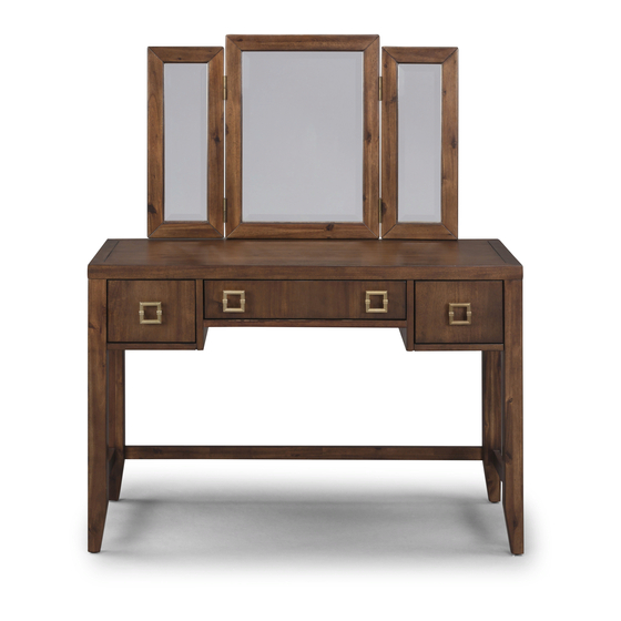
Vanity with Mirror
H.
G.
Batten
Side Panel
2 pcs.
1 pc.
K.
Mirror
1 pc.
Flat Washer
13 pcs. (+1 extra)
Cover
2 pcs. (+1 extra)
B.
Side Frame
1 pc.
M6x30
Spring Washer
Head Cap Bolt
13 pcs. (+1 extra)
13 pcs. (+1 extra)
M3.5x20
M4x30
Wood Screw (short)
Wood Screw
16 pcs. (+1 extra)
26 pcs. (+1 extra)
888-680-7460, 877-831-0319
D.
Front Rail
2 pcs.
C.
E.
Side Frame
Front Rail
1 pc.
1 pc.
L.
Drawer
2 pcs.
M.
Drawer
1 pc.
Refer to later page(s) of these
instructions for drawer assembly.
M6x40
Head Cap Bolt (long)
8 pcs. (+1 extra)
M4x30
Machine Screw
Handle
8 pcs.
4 pcs.
Advertisement

Related Manuals for Home Styles 20 05507 0070


Summary of Contents for Home Styles 20 05507 0070
- Page 1 12 pcs. (+1 extra) 2 pcs. (+1 extra) 16 pcs. (+1 extra) 26 pcs. (+1 extra) 8 pcs. 4 pcs. Tool(s) required for assembly: Phillips screwdriver, Level, Drill (8 volts or less), 3/8” Drill Bit Home Styles Customer Service: www.homestyles-furniture.com, servicedesk@homestyles-furniture.com, 888-680-7460, 877-831-0319...
- Page 2 Assembly Instructions 2/8 IMPORTANT Ÿ Use a soft cloth between these parts and the floor. Ÿ Do not use power tools above 8 volts to assemble. Ÿ Do not tighten all the bolts until each part is properly assembled. Ÿ The unit must be level to work properly.
- Page 3 Assembly Instructions 3/8 STEP 2 Cam Lock Place Top (A) upside down on a soft cloth. Attach Side Frame (F) to Top (A) with Cam Locks. (See Figure 2) Attach Front Rain (E) to unit with Cam Locks. Attach Side Frame (G) to unit with Cam Locks.
- Page 4 Assembly Instructions 4/8 STEP 4 Head Cap Bolt Attach Front Rail (D) to unit Spring Washer with Cam Lock. Flat Washer Cam Lock Attach Side Frame (C) to unit with Flat Washers, Spring Washers, Head Cap Bolts, and Cam Lock tightening bolts only halfway.
-
Page 5: Part List
Assembly Instructions 5/8 Drawer (L) Bottom Wood Screw STEP 6 Attach Drawer Front (L1) and Drawer Back (L2) to Drawer Side (L3) with Wood Screws. Roller at back Attach Drawer Side (L4) to unit with Wood Screws. STEP 7 Wood Screw (short) Slide Drawer Bottom (L5) into groove. - Page 6 Assembly Instructions 6/8 Drawer (M) Bottom STEP 10 Attach Drawer Front (M1) and Drawer Back (M2) to Drawer Side (M3) with Wood Screws. Wood Screw Roller at back Attach Drawer Side (M4) to unit with Wood Screws. STEP 11 Wood Screw Wood Screw (short) Slide Drawer Bottom (M5) into groove.
- Page 7 Assembly Instructions 7/8 STEP 13 Turn unit over to its upright position. Slide Drawers (L) and (M) into position. STEP 14 Attach Battens (H) to Mirror (K) and unit with Head Cap Bolts (long), then tighten. Level unit by adjusting the adjustable levelers on bottom of unit.
-
Page 8: Hardware List
Assembly Instructions 8/8 IMPORTANT Ÿ To help reduce the risk of the unit tipping over, the Tip-over Restraint must be installed following these instructions exactly. STEP 15 Anchor in wall Bracket Wall Screw Pre-drilled hole at top of unit on wall Place unit at desired location. - Page 9 Buff with a dry clean cloth. Home Styles will provide replacements free of charge for missing or damaged hardware or parts within 30 days of purchase. Digital images of the defective parts may be required. If the product was not purchased from an authorized retail affiliate, Home Styles is under no obligation to provide replacement parts.
Need help?
Do you have a question about the 20 05507 0070 and is the answer not in the manual?
Questions and answers