
Related Manuals for AMS USB I&P Box


Summary of Contents for AMS USB I&P Box
- Page 1 USB I&P Box User Manual USB Interface & Programming Box Evaluation Programmer for SPI & I2C Interface www.ams.com Revision 1.2 / 06/10/2014 page 1/9...
-
Page 2: Table Of Contents
GUI Overview ........................7 Firmware Update ........................8 Ordering Information ......................8 Copyright ............................. 9 Disclaimer ............................9 Revision History Revision Date Owner Description 21.01.2014 AZEN Initial revision 06.08.2014 Minor changes 06.10.2014 AZEN Updated Compatible Products www.ams.com Revision 1.2 / 06/10/2014 page 2/9... -
Page 3: General Description
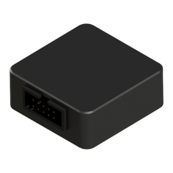
For programming a Magnetic Position Sensor the sensor should be mounted on a PCB to get connected with all the necessary pins of the sensor. For Position Sensors, ams provides Adapterboards where an easy access from the Sensor to the USB I&P Box is possible (not in the Tool-Kit included) Figure 1: USB I&P Box... -
Page 4: Hardware
14-bit On-Axis Magnetic Rotary Position Sensor AS5048A 14-bit Angular Position Sensor with SPI Interface AS5048B 14-bit Angular Position Sensor with I2C Interface AS5050A Low Power 10-Bit Magnetic Position Sensor AS5055A Low Power 12-Bit Magnetic Position Sensor www.ams.com Revision 1.2 / 06/10/2014 page 4/9... -
Page 5: Pin-Out
Note: The interface voltage of the USB I&P Box is 3,3V. Use the 3,3V mode when connecting to a position sensor board. First steps with the USB I&P Box The first steps to get started with the USB I&P Box are described below in Figure www.ams.com Revision 1.2 / 06/10/2014 page 5/9... - Page 6 Connect the right wires of the USB I&P For using the right wires Connector cable to your magnetic position please refer to Table 3 sensor Open the USB I&P Software Choose the right Device Ready to start www.ams.com Revision 1.2 / 06/10/2014 page 6/9...
-
Page 7: Software
B: Check if the Programmer will be detected (or there is no bootloader on the I&P Box) C: For firmware updates click on Help and Firmware Update, for further Information about this topic refer to www.ams.com Revision 1.2 / 06/10/2014 page 7/9... -
Page 8: Firmware Update
Search your computer for the new firmware file and click at it After that the firmware installs by itself and the update is successful Ordering Information Table 4: Ordering Information Ordering Code Description USB I&P Box USB Interface & Programming box for I2C/SPI www.ams.com Revision 1.2 / 06/10/2014 page 8/9... -
Page 9: Copyright
USB I&P Box User Manual Copyright Copyright ams AG, Tobelbader Strasse 30, 8141 Unterpremstätten, Austria-Europe. Trademarks Registered. All rights reserved. The material herein may not be reproduced, adapted, merged, translated, stored, or used without the prior written consent of the copyright owner.
Need help?
Do you have a question about the USB I&P Box and is the answer not in the manual?
Questions and answers