
Related Manuals for AMS TCS3701


Summary of Contents for AMS TCS3701
- Page 1 User Guide UG000418 TCS3701 ALS/Color and Proximity Sensor for Use Behind OLED Displays Evaluation Kit TCS3701 EVM v1-00 • 2019-Jan-11...
-
Page 2: Table Of Contents
Document Feedback TCS3701 Content Guide Content Guide Introduction ........3 Device ID Information ........ 11 Log Status and Control Information ... 11 Kit Content ............ 3 “ALS” Tab ........... 12 Ordering Information ........4 “Prox” Tab ..........15 Getting Started ....... 5 Resources ........ -
Page 3: Introduction
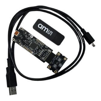
Document Feedback TCS3701 Introduction Introduction The TCS3701 evaluation kit comes with everything needed to evaluate the TCS3701 . The device features ambient light and color (RGB) sensing in parallel with proximity detection. Kit Content Figure 1 : Evaluation Kit Contents... -
Page 4: Ordering Information
Document Feedback TCS3701 Introduction Ordering Information Ordering Code Description TCS3701 ALS/Color and Proximity Sensor for Use Behind TCS3701 EVM OLED Displays Evaluation Kit Demo Kit Manual • PUBLIC UG000418 • v1-00 • 2019-Jan-11 │ 4... -
Page 5: Getting Started
The balance of this document identifies and describes the controls available on the GUI. In combination with the TCS3701 datasheet, the QSG and application notes available on the ams website, there should be enough information to allow evaluation of the TCS3701 device. -
Page 6: Hardware Description
Hardware Description Hardware Description The hardware consists of the EVM Controller, the TCS3701 EVM daughter card, and a USB interface cable. The EVM controller board provides power and I2C communication to the daughter card through a seven pin connector. When the EVM controller is connected to the PC through USB, a green LED on the board flashes once on power up to indicate the system is getting power. -
Page 7: Software Description
Document Feedback TCS3701 Software Description Software Description The main window (Figure 3) contains the system menus, system level controls, device information and logging status. The ALS tab contains controls for the light sensing function. The Prox tab contains settings for the proximity function. The application polls the ALS and proximity raw data continuously and calculates the Lux, CCT, and prox standard deviation values. -
Page 8: System Menus
Document Feedback TCS3701 Software Description If the EVM board is disconnected from the USB bus while the program is running it displays an error message and then terminates. Reconnect the EVM board and restart the program. System Menus At the top of the window there are pull-down menus labeled “File”, “Log”, and “Help”. The File menu provides basic application-level control. - Page 9 Document Feedback TCS3701 Software Description 4.2.2 Log Menu The Log menu is used to control the logging function and to save the log data to a file. Log data is accumulated in memory until it is discarded or written to a data file.
-
Page 10: System Level Controls
TCS3701 device. The Power On checkbox controls the PON function of the TCS3701 . When this box is checked, the power is on and the device can operate. When this box is unchecked, the power is off and the device does not operate (The control registers can still be written, but the device does not function). -
Page 11: Device Id Information
Document Feedback TCS3701 Software Description Device ID Information The lower left corner of the window displays the ID number of the EVM Controller board, identifies the device being used and displays the ID of the device. Log Status and Control Information... -
Page 12: Als" Tab
Document Feedback TCS3701 Software Description “ALS” Tab The main portion of the screen contains a tab labeled ALS. The controls in this tab are divided into 3 sections, each performing a separate function. Figure 9 : ALS Tab 4.7.1 ALS Controls The left side of the ALS tab contains controls to set various ALS settings. - Page 13 PC and polling rate of the GUI program, the GUI does not display every sample, since the actual TCS3701 is operating faster than the GUI can display and log the data. This is not normally an issue, since the operating environment is not rapidly changing. The Raw FIFO Log is a special function that is designed to capture all of the ALS Data for Channels 0 and 1, without skipping any data.
- Page 14 The XML file must contain all the required Lux equation elements to be loaded. The format of the file follows the standard XML format and is as follows: <?xml version="1.0" encoding="utf-8"?> <!-- Device:TCS3701 Saved:1/9/2019 2:10:00 PM --> <luxeq> <eq_values>...
-
Page 15: Prox" Tab
“Prox” Tab The main portion of the screen contains a tab labeled Prox. The controls on this tab control the operation of the Proximity function of the TCS3701. Demo Kit Manual • PUBLIC UG000418 • v1-00 • 2019-Jan-11... - Page 16 Document Feedback TCS3701 Software Description Figure 11 : Prox Tab 4.8.1 Prox Controls The left side of the Prox tab contains controls to set various Prox settings. The PPULSE controls the number of pulses used for each prox cycle. The number of pulses is the PPULSE value plus 1 and is displayed immediately to the right of the box.
- Page 17 15 consecutive proximity values out of range Information The Offset Range Extension feature of the TCS3701 is known to cause the PDATA values to drift over time. Use of this feature IS NOT recommended. The Enable control in the Offset range extension group box enables the coarse offset range when checked.
- Page 18 Document Feedback TCS3701 Software Description The Disable APC control disables the automatic pulse control (APC) function. When this function is active, the range of the PDATA value is 0-1023. The Dropdown control in the Prox Filter group box enables and disables the Proximity Filter. This causes a running average of 1 (Disabled), 2, 4, or 8 samples to be reported in the PDATA register.
-
Page 19: Resources
Resources For additional information regarding the TCS3701, please refer to the datasheet. For information regarding the installation of the TCS3701 EVM host application software please refer to the TCS3701 EVM Quick Start Guide. Designer’s Notebooks dealing with various aspects of optical measurement and optical measurement applications are available. -
Page 20: Revision Information
Document Feedback TCS3701 Revision Information Revision Information Changes from previous version to current revision v1-00 Page Initial Release ● Page and figure numbers for the previous version may differ from page and figure numbers in the current revision. ● Correction of typographical errors is not explicitly mentioned. -
Page 21: Legal Information
AG shall not be liable to recipient or any third party for any damages, including but not limited to personal injury, property damage, loss of profits, loss of use, interruption of business or indirect, special, incidental or consequential damages, of any kind, in connection with or arising out of the furnishing, performance or use of the technical data herein.
Need help?
Do you have a question about the TCS3701 and is the answer not in the manual?
Questions and answers