AMS AS5600 Operation Manual
12-bit programmable contactless potentiometer
Hide thumbs
Also See for AS5600:
- Operation manual (12 pages) ,
- Manual (14 pages) ,
- User manual (13 pages)

Related Manuals for AMS AS5600


Summary of Contents for AMS AS5600
- Page 1 Operation Manual: AS5600-SO_EK_AB AS5600 12-bit Programmable Contactless Potentiometer www.ams.com Revision 1.0 / 05.05.2014 page 1/10 Arrow.com. Downloaded from...
-
Page 2: Table Of Contents
Mechanical Setup ......................... 5 Electrical Setup ........................5 2.4.1 3-Wire Mode ......................... 5 2.4.2 C Mode ..........................6 AS5600 Configuration ......................6 Programming the output range .................... 6 Programming a configuration ....................6 3.2.1 Low Power Mode ......................... 7 3.2.2 Hysteresis .......................... -
Page 3: General Description
Find the datasheet online at http://ams.com/eng/AS5000-MD6H-1 Getting Started The AS5600 adapter board is ideal for rapid setup of a contactless potentiometer. Additionally to the adapter board, a sensor magnet in a mechanical setup is required. A reference magnet comes with the kit. -
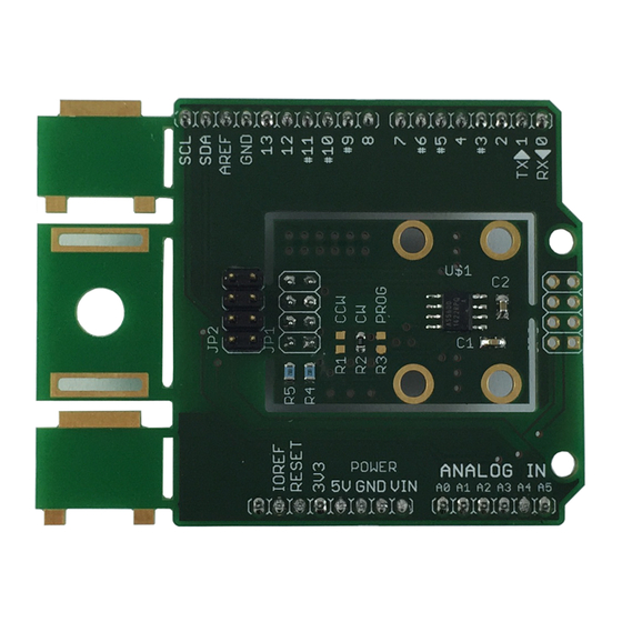
Page 4: Adapter Board Description
Analog Output default, PWM possible, Is used for programming option B 2.2 Adapter Board Description The AS5600 is connected over the dual-row 2.54mm 4-pin header footprint. Connect the desired pins of the AS5600 using the headers and resistors. Figure 1:... -
Page 5: Mechanical Setup
Sensor Magnet (d6x2,5) AS5600 The magnet should be aligned by reading the output of the AGC register of the AS5600. For optimal alignment, the AGC value is in the middle of the AGC range. Note: If the magnetic field seen by the AS5600 is below 8mT, the output is switched off and permanent angle programming is not possible. -
Page 6: I 2 C Mode
Using the board in I2C Mode µC AS5600 Configuration All options to configure the AS5600 are shown below. The AS5600 operates with a default configuration if no configuration was programmed. 3.1 Programming the output range To adjust a custom angle to the full output range or to modify the Zero Position of the device, the AS5600 must be programmed. -
Page 7: Low Power Mode
3.2.6 Watchdog If the watchdog is active, the AS5600 automatically enters Low Power Mode 3 after one minute if the output value stays within a threshold of 4 LSB. -
Page 8: Layout And Board Dimensions
10uF 1740614 1833804 Note6: Farnell Farnell 2008343 AS5600 I2C Address is 0x36h 4.2 Layout and Board Dimensions The PCB layout is shown below in Figure Figure 6: Adapterboard layout 4.3 Bill of Materials The BOM of the pcb is below in... -
Page 9: Evaluation Tools
Smart Potentiometer IC Evaluation tools To configure the AS5600, no dedicated programmer is needed. For fast setup time the USB I&P Box can be used to configure the AS5600 over I C. The USB I&P Box can be ordered from the ams webpage. -
Page 10: Copyright
AG shall not be liable to recipient or any third party for any damages, including but not limited to personal injury, property damage, loss of profits, loss of use, interruption of business or indirect, special, incidental or consequential damages, of any kind, in connection with or arising out of the furnishing, performance or use of the technical data herein.
Need help?
Do you have a question about the AS5600 and is the answer not in the manual?
Questions and answers