Table of Contents

Related Manuals for AMS Osram USB I&P Box


Summary of Contents for AMS Osram USB I&P Box
- Page 1 USB interface and programming box User Guide Evaluation programmer for SPI and I²C interface Published by ams-OSRAM AG Tobelbader Strasse 30, 8141 Premstaetten, Austria Phone +43 3136 500-0 ams-osram.com © All rights reserved...
-
Page 2: Table Of Contents
USB interface and programming box Table of contents Table of contents Introduction .............. 3 Kit content ................4 Ordering information ............... 4 Compatible products ............... 5 Getting started ............6 Firmware update ..............9 Connecting compatible products ......10 AS5013 ................. 10 AS5047D/AS5147/AS5047P/AS5147P ........ -
Page 3: Introduction
To program a sensor, it should be mounted on a PCB / Socket to ensure a proper connection to all necessary pins. ams OSRAM provides Adapter boards where easy access from the Sensor to the USB I&P Box is possible (not included with the Tool-Kit). -
Page 4: Kit Content
Contains the USB I&P Box Software and manuals. USB flash To get latest SW / FW and Manuals please refer to drive ams-osram.com Ordering information Ordering code Description USB I&P Box USB interface & programming tool for sensors with I²C or SPI interface Eval Kit Manual •... -
Page 5: Compatible Products
USB interface and programming box Introduction Compatible products Table 2: Compatible products Product Description Adapterboard available AS5013 Low power integrated hall IC for human interface applications AS5047D 14-bit on-axis magnetic rotary position sensor AS5047P 14-bit on-axis magnetic rotary position sensor AS5048A 14-bit angular position sensor with SPI interface AS5048B... -
Page 6: Getting Started
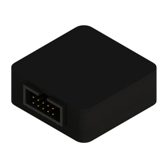
USB interface and programming box Getting started Getting started The pin-out of the USB I&P box is shown below. Table 3: USB I&P box pin-out and wire description Pin # Color Definition SPI mode Brown 5V supply Not used 3.3V supply Positive power supply Orange SPI-CS(0) - Page 7 USB interface and programming box Getting started Figure 2: First steps with the USB I&P box Getting started with your programmer Install the USB I&P Software on your computer Connect your USB I&P Box to your computer via USB cable Connect the right wires of the USB I&P For using the right wires Connector cable to your magnetic position...
- Page 8 USB interface and programming box Getting started Also included in your USB I&P Tool is a USB stick with the software and firmware. The software is needed to program a supported sensor on your computer. After you copied the software from the USB stick to your computer, please click on it and follow the instructions of the Install Wizard through the installation procedure.
-
Page 9: Firmware Update
USB interface and programming box Getting started Figure 4: Screenshot of the GUI starting page while programmer connected Firmware update • Connect your I&P Box to your Computer and open the Software. • Click on Help and Firmware Update. • Search your computer for the new firmware file and click at it. -
Page 10: Connecting Compatible Products
USB interface and programming box Connecting compatible products Connecting compatible products AS5013 Figure 5: AS5013 Open/Close J1 for choosing I²C slave address 0x40 or 0x41. Connect the USB I&P Box with the AS5013-QF_EK_AB using the 10-way cable. Connect the USB I&P Box using the USB cable to Computer. Eval Kit Manual •... -
Page 11: As5047D/As5147/As5047P/As5147P
USB interface and programming box Connecting compatible products AS5047D/AS5147/AS5047P/AS5147P Figure 6: AS5047D/AS5147/AS5047P/AS5147P Short J1 on the adapterboard to set-up the 3V3 mode. Connect the USB I&P Box with the AS5x47_EK_AB using the 10-way cable. Place the RMH05 over the adapterboard. Connect the USB I&P Box to the PC, using the USB cable. -
Page 12: As5050A/As5055A
USB interface and programming box Connecting compatible products AS5050A/AS5055A Figure 7: AS5050A/AS5055A Short JP1 either on 3-wire SPI mode or 4-wire SPI mode. Connect the USB I&P Box with the AS5050 / AS5055-AB using the 10-way cable. Place the RMH05 over the adapterboard. Connect the USB I&P Box to the PC, using the USB cable. -
Page 13: As5048A/As5048B
USB interface and programming box Connecting compatible products AS5048A/AS5048B Figure 8: AS5048A/AS5048B Check first if you are using AS5048A or AS5048B. AS5048A uses SPI and AS5048B I²C interface. Connect the USB I&P Box with the AS5048A/B-AB using the 10-way cable. Place the RMH05 over the adapterboard. -
Page 14: As5100
USB interface and programming box Connecting compatible products AS5100 Figure 9: AS5100 Close J1 for 3V3 supply. Connect the USB I&P Box with the AS5100-SO_EK_AB using the 10-way cable. Use an RMH Kit + Magnet to get a stable angle readout. Connect the USB I&P Box to the PC, using the USB cable. -
Page 15: As5116
USB interface and programming box Connecting compatible products AS5116 Figure 10: AS5116 G ND U A RT V DD 5 Note: Th e so cket boar d has a buffer-cir cu itr y included, which is not on the Adapter Board . A Socket Board can be connected directly to the I&P Box to program an Adapter Board. -
Page 16: As5510
USB interface and programming box Connecting compatible products AS5510 Figure 11: AS5510 JP1 closed - I²C address = 57h; JP1 open - I²C address = 56h Connect the USB I&P Box with the AS5510-AB using the 10-way cable. Place a 2-pole magnet over the AS5510. Connect the USB I&P Box to the computer using the USB cable. -
Page 17: As5600
USB interface and programming box Connecting compatible products AS5600 Figure 12: AS5600 Short J1 on the adapterboard to set-up 3V3 mode. Connect the USB I&P Box with the AS5600_SO_EK_AB using the 10-way cable. Place the RMH05 over the adapterboard. Connect the USB I&P Box to the PC, using the USB cable. The USB device is detected by Windows and by the AS560x Demo Software. -
Page 18: As5600L (For Wlcsp-15 And Soic-8 Package)
USB interface and programming box Connecting compatible products AS5600L (for WLCSP-15 and SOIC-8 package) Figure 13: AS5600L (for WLCSP-15 and SOIC-8 package) Short J1 on the adapterboard to set-up 3V3 mode. Connect the USB I&P Box with the AS5600L_SO_EK_AB using the 10-way cable. Place the RMH05 over the adapterboard. -
Page 19: As5601
USB interface and programming box Connecting compatible products 3.10 AS5601 Figure 14: AS5601 Short J1 on the adapterboard to set-up 3V3 mode. Connect the USB I&P Box with the AS5601_SO_EK_AB using the 10-way cable. Place the RMH05 over the adapterboard. Connect the USB I&P Box to the PC, using the USB cable. -
Page 20: As5200A/L
USB interface and programming box Connecting compatible products 3.11 AS5200A/L Figure 15: AS5200A/L Short J1 and J2 on the adapterboard to set-up 3V3 mode. Otherwise 5V supply has to be used. Connect the USB I&P Box with the AS5200A/L-MF_EK_AB using the 10-way cable. Place the RMH05 over the adapterboard. - Page 21 USB interface and programming box Connecting compatible products Figure 16: AS5200A/L Set J1&J2 and the jumper on the adapter to 3V3 to use 3.3V supply. To use 5V supply leave J1&J2 open and set 5V on the adapter PCB. Connect the adapter with the AS5200A/L-MF_EK_AB Connect the adapter with the USB I&P Box Eval Kit Manual •...
-
Page 22: As5247
USB interface and programming box Connecting compatible products 3.12 AS5247 Figure 17: AS5247 Connect the USB I&P Box using the USB cable to the PC. Connect the USB I&P Box with the AS5247-SO_EK_AB using the 10-way cable. Place the RMH05 over the adapterboard. Eval Kit Manual •... -
Page 23: As5047U/As5147U
USB interface and programming box Connecting compatible products 3.13 AS5047U/AS5147U Figure 18: AS5047U/AS5147U Connect the USB I&P Box using the USB cable to the PC. Connect the USB I&P Box with the AS5047U / AS5174U adapterboard using the 10-way cable. Place the RMH05 over the adapterboard. -
Page 24: As5247U
USB interface and programming box Connecting compatible products 3.14 AS5247U Plug the AS5247U-TQ_EK_AB directly with the populated 10-way connector to the USB I&P Box. It is possible to extend the connections with cables. Maximum wire length is 30 cm. Figure 19: AS5247U USB Connection to host PC with to be used with I&P Box software. -
Page 25: As8579
USB interface and programming box Connecting compatible products 3.15 AS8579 Figure 20: AS8579 Connect the USB I&P Box with the AS8579-TS_EK_DB using the P1 – Connector. Connect the USB I&P Box using the USB cable to Computer. 3.16 AS6221 Figure 21: AS6221 Set Jumper to select the I²C slave address 0x44 or 0x45. -
Page 26: Revision Information
Draft / Preliminary: The draft / preliminary status of a document indicates that the content is still under internal review and subject to change without notice. ams-OSRAM AG does not give any warranties as to the accuracy or completeness of information included in a draft / preliminary version of a document and shall have no liability for the consequences of use of such information. -
Page 27: Legal Information
No obligation or liability to recipient or any third party shall arise or flow out of ams- OSRAM AG rendering of technical or other services.
Need help?
Do you have a question about the Osram USB I&P Box and is the answer not in the manual?
Questions and answers