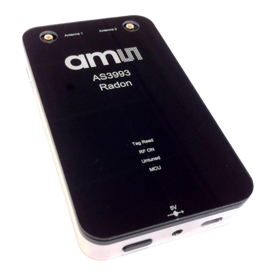
Summary of Contents for AMS Radon AS3993
- Page 1 Application Note: Radon Demo Reader – HW Description AS3993 Radon Demo Reader – Hardware Description www.ams.com Revision 1.2 / 21/02/2014 page 1/13...
-
Page 2: Table Of Contents
Figure 10 - SPI Interface Connector Pinout ..................11 Figure 11 - RF Testpoint Adapter (not included in the demo kit) ............11 Figure 12 - RF Test Point Description ....................12 Figure 13 - SMB Plug (Female) ......................12 www.ams.com Revision 1.2 / 21/02/2014 page 2/13... -
Page 3: General Description
The plastic cover is held by magnets and can be lifted to allow access the PCB. The PCB is mounted by four screws to the metallic base. Underneath the PA an adhesive By desoldering zero ohm resistors www.ams.com Revision 1.2 / 21/02/2014 page 3/13... -
Page 4: Kit Content
6) The Radon reader is listed in the main window and the state shows Online in green letters. 7) To scan for tag click on the Start Scan button in the lower left corner of the main window. Adhere to local RF regulations. www.ams.com Revision 1.2 / 21/02/2014 page 4/13... -
Page 5: Hardware Description
Balun. The attenuator has an attenuation of 7dB and an input/output impedance of 49 ohms. The pre-amplifier (SGC2363Z) increases the RF power to approx. 1.8 dBm. The pre-amplifier has a dedicated regulated voltage (AS1362) supply of 3.3V. www.ams.com Revision 1.2 / 21/02/2014 page 5/13... -
Page 6: Power Supply
MCU without the DC power supply. The pre-amplifier and the AS3993 are supplied by a fixed output voltage (3.3V) version of AS1362. The LDO output voltage for the PA is adjustable and is set to 3.6V. www.ams.com Revision 1.2 / 21/02/2014 page 6/13... -
Page 7: Mcu
In case the USB is connected before the external DC supply the controller immediately starts with self-check. But at this point the AS3993 is not yet supplied. An error message is display in the GUI. www.ams.com Revision 1.2 / 21/02/2014... -
Page 8: Bootloader
Description /MCLR Master Clear (device Reset) Input. VCMU Power supply GND_DIG Ground PGED1 Data Line PGEC1 Clock Line UART_TX Used for UART logging in (RP24) the bootloader Figure 5 - Debug Interface Pinout www.ams.com Revision 1.2 / 21/02/2014 page 8/13... -
Page 9: Fw Programming
Important voltages can be measured at the following test points. Please note that the voltages VAPC and VMIX are valid only during scanning for tags. Testpoint Pin # Description J1-1 VUSB, 5V from USB J1-2 5V from DC jack J17-1 J17-2 J11-1- VEXT www.ams.com Revision 1.2 / 21/02/2014 page 9/13... -
Page 10: Signal Test Points
Analog Mixer DC output to determine the self-jamming level. 3.6.3 SPI Interface Signals On J10, J26 and J27 AS3993 signal lines and the SPI signals can be monitored. Figure 9 - Locating the SPI Interface Connector www.ams.com Revision 1.2 / 21/02/2014 page 10/13... -
Page 11: Rf Test Points
If the adapter is connected to the coax socket the RF track on the PCB is disconnected. Please note that the coax sockets have limited plug/unplug cycles of 500 times. Pin # Description Single ended AS3993 output power after the external attenuator. Pre-amplifier output power www.ams.com Revision 1.2 / 21/02/2014 page 11/13... -
Page 12: Antenna Connections
The Radon reader is intended for engineering usage to demonstrate the AS3993. Before turning the Radon reader ON please check your local RF regulations and configure the reader accordingly. Always connect a RF load to the antenna port in use, www.ams.com Revision 1.2 / 21/02/2014 page 12/13... -
Page 13: Copyright
No obligation or liability to recipient or any third party shall arise or flow out of ams AG rendering of...


Need help?
Do you have a question about the Radon AS3993 and is the answer not in the manual?
Questions and answers