Advertisement
Quick Links
Advertisement

Related Manuals for AMS Osram AS1170


Summary of Contents for AMS Osram AS1170
- Page 1 Sensing is life AS1170 EVK GUIDE Hardware Description and SW examples For internal use...
- Page 2 GUI and Driver Installation step by step guideline 1) Unzip/Extract SW package to local hard drive 2) Connect Board via µUSB cable to AS1170 EVK 3) Open Device Manager and search for “USB to UART Bridge” 4) Select “Update Driver” from your local drive and select folder of step #1 (location of extracted SW package) 5) After Driver is successfully installed launch AS1170_GUI.exe 6) Correct installation will show green status lamp on bottom right of GUI SW Step 6...
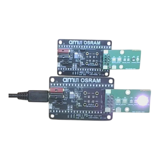
- Page 3 AS1170 EVK Jumper and Terminal Description Layout and Jumper Description Input Description OPTIONAL: ONLY USE for high LED currents (>450mA). Use lab power supply and remove J6 VBAT 2.7V – 4.4V Strobe button External LED Board connector When used remove J5 to disconnect on-board LEDs MCU Board Connector (SCL, SDA, Strobe, 3V3) MCU Board Connector Open/Disconnect onboard SFH41747 LEDs...
- Page 4 AS1170 EVK Schematic Circuit Diagram For internal use...
- Page 5 AS1170 EVK Layout (1) All layers Top: red IN1: yellow (GND) IN2: light blue (VBAT) Bot: dark blue For internal use...
- Page 6 IR LED Break-out board schematic Header P1 connected to J1 of AS1170 EVK This break-out board can be used to assemble and test several different LED options. Note: if break-out board is connected, make sure J5 of mainboard is removed to disable on-board LEDs For internal use...
- Page 7 AS1170 GUI SW First Steps 1) Connect EVK with µUSB Cable to USB Port of EVK 2) Start AS1170_GUI.exe 3) If USB_UART Driver is installed successfully green indicator will appear 4) Press “Configuration Button” to access device setup window For internal use...
- Page 8 AS1170 GUI SW How to configure “Indicator Mode/PWM”: 1) Enable “Indicator Mode/PWM” 2) Configure LED_OUT Current Setting • Indicator PWM 4/16 (=25% Duty Cycle) • LED 1 Current 199.5mA* • LED 2 Current 199.5mA* 3) Enable “Out On” Checkbox • LED enabled with ~400mA (LED_OUT1 and LED_OUT2 combined on break-out board •...
- Page 9 AS1170 GUI SW How to configure “Flash Mode”: 1) Enable “Flash Mode” 2) Configure LED_OUT Current Setting • LED 1 Current 199.5mA* • LED 2 Current 199.5mA* 3) Configure “LED Timings” • Select LED ON Time “2ms” 4) Enable “Out On” Checkbox •...
- Page 10 Side by Side comparison aO LED with competitor LED AS1170 indicator mode used like shown on slide 8 aO LED with 400mA and 25% Duty Cycle Competitor LED with 400mA and 25% Duty Cycle For internal use *Note: Pictures taken with integrated laptop camera...
- Page 11 BACKUP Slides (configuration details for external MCU) For internal use...
- Page 12 I2C ADDR Selection For internal use...
- Page 13 I2C Device Address (A-select pin) EVK Default setting: Pin I2C_ADDR = 0 → I2C address = 0x30 (7-bit) → R6 = 0R & R1 = NC Alternative setting: Pin I2C_ADDR = 1 → I2C address = 0x32 (7-bit) → R1 = 0R & R6 = NC Settings: Set I2C_ADDR pin to 0 = 0x30 I2C address //EVK default setting with R6 = 0R and R1 = NC...
- Page 14 Strobe function For internal use...
- Page 15 Strobe input definition via register 07h AS1170 can be activated with an input via pin STROBE or via I2C command by setting OUT_ON = “1” Reg 07h, bit 6: “Strobe type” • Default setting → level sensitive: AS1170 is reacting on rising and falling edge of the strobe signal as long the strobe pulse is shorter than the flash timeout timer •...
- Page 16 Flash mode settings and examples For internal use...
- Page 17 Current setting & Flash timeout timer calculation Default Register Address = 0x10 Single Flash: Mode setting: mode_setting “11” / auto_strobe = 0 After a flash is triggered register bits “mode_setting” and “out_on” are reset to “0”. Hence to retrigger a new flash using Strobe pin, an I2C command is required to set the mode_setting[1:0] = 3 and out_on=1.
- Page 18 Single flash with external strobe Programming example single flash yellow: STROBE blue: LED_OUT red: ILED current green: Vbat/Vin For internal use...
- Page 19 Multiple flash pulses with external strobe Programming example multiple flash pulses yellow: STROBE blue: LED_OUT red: ILED current green: Vbat/Vin For internal use...
- Page 20 AS1170 example configuration codes For internal use...
- Page 21 AS1170 configuration code example Multiple Flash pulses , external Strobe / level sensitive, auto_strobe = 1 (no re-configuration) AS1170 power on reset (apply VIN) #7bit I2C adress = 0x30 i2c_write(ADDR 07h, Reg.Strobe_Signalling, 0xC0 ) // strobe_type = 1 / level sensitive , strobe_on = 1 / external STROBE input enabled in flash mode i2c_write(ADDR 05h, Reg.Flash_Timer, 0x80) // flash timeout timer set to 129ms i2c_write(ADDR 01h, Reg.CURRENT_SET_LED1, 0x7F )
- Page 22 AS1170 configuration code example Single Flash , external Strobe / level sensitive, auto_strobe = 0 (re-configuration after flash triggered) AS1170 power on reset (apply VIN) #7bit I2C adress = 0x30 i2c_write(ADDR 07h, Reg.Strobe_Signalling, 0xC0 ) //strobe_type = 1 / level sensitive , strobe_on = 1 / external STROBE input enabled in flash mode i2c_write(ADDR 05h, Reg.Flash_Timer, 0x23) //flash timeout timer set to 36ms (default configuration) i2c_write(ADDR 01h, Reg.CURRENT_SET_LED1, 0x7F )
Need help?
Do you have a question about the Osram AS1170 and is the answer not in the manual?
Questions and answers