Table of Contents
Advertisement
Quick Links
CONVENIENCE
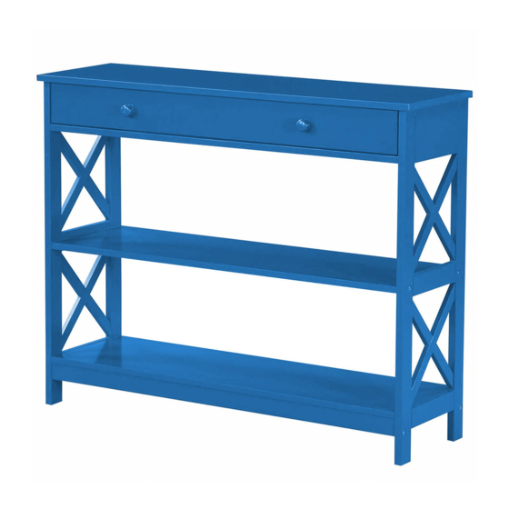
Oxford 1 Drawer Console Table
Assembly instructions
We have designed our furniture with you, the customer in mind. Our clear, easy to follow step
by step instructions will guide you through the project from start to finish. Feel confident that
this will be a fun and rewarding project. The final product will be a quality piece of furniture
that will together smoothly and give years of enjoyment.
Please do not return to the store
Broken or missing Hardware? Need help
with Assembly?
Our Illinois based customer service team is ready to help with any problems or
questions you may have. Please give us a call (Toll Free)
at 1800-468-6447, or email us at parts@convenience-concepts.com.
Normal hours of Operation: M - F* 8 am - 4 pm CST
* Excludes Holidays.
This product's warranty is only valid through authorized dealers.
CONCEPTS
203295
Page 1 of 5
Advertisement
Table of Contents

Related Manuals for convenience concepts Oxford 203295


Summary of Contents for convenience concepts Oxford 203295
- Page 1 CONVENIENCE CONCEPTS Oxford 1 Drawer Console Table 203295 Assembly instructions We have designed our furniture with you, the customer in mind. Our clear, easy to follow step by step instructions will guide you through the project from start to finish. Feel confident that this will be a fun and rewarding project.
- Page 2 Top Panel Right Side Panel Back Support Bar Support Bar Shelf Right Drawer Side Panel Drawer Back Panel Shelf Drawer Front Drawer Support Bar A 17pcs B 17pcs C 4pcs D 13pcs E 4pcs F 1pc G 1pc I 2pcs H 2pcs Cam Bolt Cam Lock Wooden Dowel Screw Small Screw Right Glider...
- Page 3 Step 1 E×4 F×1 G×1 Step 2 D×6 Step 3 1. Screw cambolts (A) into left side panel 1 . 2. Connect back support bar 4 and support bar 6 to left side panel 1 using cambolts (A) and camlocks (B). 3.
- Page 4 Step 4 Cambolt hole Part 4 A×4 Cambolt hole B×4 Part 6 C×2 L×4 M×4 Q×1 1. Screw cambolts (A) into left side panel 2 . 2. Connect right side panel 2 to unit using cambolts (A), camlocks (B),bolts (L) and lock nuts (M). Step 5 1.
- Page 5 Step 7 1. Carefully insert drawer into unit. P×8 Step 8 & right panel 2 using small screw (O) 2. Place unit against wall and mark bracket holes. 3. Drill holes in wall sligh tly smaller than anchor (H) and gently tap anchors into holes. 4.
Need help?
Do you have a question about the Oxford 203295 and is the answer not in the manual?
Questions and answers