Table of Contents
Advertisement
Quick Links
Advertisement
Table of Contents

Related Manuals for Da-Lite TENSIONED DIRECTOR ELECTROL


Summary of Contents for Da-Lite TENSIONED DIRECTOR ELECTROL
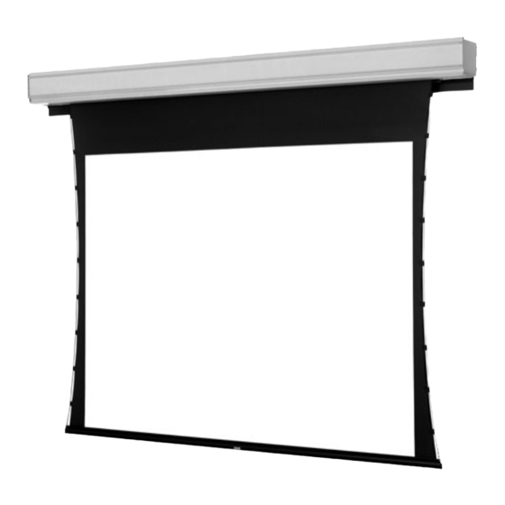
- Page 1 POWER PRESENTATION PRODUCTS Instruction Book for DA-LITE SCREEN COMPANY, INC. 3100 North Detroit Street Post Office Box 137 ® TENSIONED DIRECTOR ELECTROL Warsaw, Indiana 46581-0137 Phone: 574-267-8101 800-622-3737 Fax: 574-267-7804 www.da-lite.com e-mail: info@da-lite.com...
-
Page 2: Important Safety Instructions
5. Install electric hook up that applies to your unit. Make sure to review your electrical installation checklist and wiring diagram (included) for either 120 volt switch, 220/240 volt switch, or DRC low voltage control. NOTE: Screen has been internally wired at Da-Lite. Wiring designated “external” is completed by installer conforming to local and national codes. -
Page 3: Access Door Installation
Surface travel is stopped automatically in the fully opened and closed positions by limit switches that are properly adjusted at Da-Lite. Should it be necessary to adjust for more or less drop of picture, proceed in the following manner: NOTE: Use a screw driver or Allen wrench to make adjustments. - Page 4 3. Turn the white “down” limit switch (Fig. 2) one-quarter turn clockwise. Test by raising picture surface approximately two feet, then lower again. Repeat until desired picture surface position is attained. TENSIONED DIRECTOR ELECTROL INSTRUCTIONS RED (UP) NOTE: Electrical connections on right end of...
-
Page 5: Wiring Diagram
TENSIONED DIRECTOR ELECTROL INSTRUCTIONS RED (UP) NOTE: Electrical connections on left end of case. BLACK BLACK (DOWN) WHITE WHITE PURPLE 120V WIRING DIAGRAM GREEN RELAY BLACK & YELLOW TO JUNCTION BOX MOUNTED IN SCREEN BLACK DOOR SWITCH CASE, IN WHICH INTERNAL WIRING... - Page 6 TENSIONED DIRECTOR ELECTROL INSTALLATION 7-1/4" VARIABLE POSITION CASE LENGTH MOUNTING BRACKET 7-1/4" 7-5/8" ELECTRICAL JUNCTION BOX MOTOR END 7-5/8" 9-1/4" 3/8" THREADED ROD (NOT INCLUDED) ATTACHED TO MOUNTING BRACKET 7-1/4" FINISHED CEILING SELF-TRIMMING FLANGE 8-3/4"...
-
Page 7: Troubleshooting
TROUBLESHOOTING SYMPTOM CAUSE SOLUTION 1. Screen will not operate or will not go (a) Blown facility fuse. (a) Replace facility fuse. “down”. Motor does not hum. (b) Tripped facility circuit breaker. (b) Reset facility circuit breaker. (c) No power to operating switch or (c) Check above. - Page 8 TROUBLESHOOTING SYMPTOM CAUSE SOLUTION 4. Door does not close. (a) Open door limit switch. (a) Replace switch. 5. “Down” limit switch incorrect. (a) “Down” limit switch out of (a) See installation instructions. adjustment. 6. Noise. (a) Squeaking, rubber end plug rubbing (a) Center roller in case.