Table of Contents
Advertisement
Advertisement
Table of Contents

Related Manuals for Hioki 8420-51


Summary of Contents for Hioki 8420-51
- Page 1 QUICK START MANUAL 8420-51 8421-51 8422-51 MEMORY HiLOGGER...
-
Page 3: Table Of Contents
Contents Contents Introduction ..............1 Safety Notes ..............2 1 Identification of Controls and Indicators Identification of Controls and Indicators ..... 4 2 Display Screen and Setting Items Status Screen ............. 9 Channel Screen ..........10 Waveform Screen ..........11 3 Measurement Examples Voltage Measurement ........ - Page 4 Quick Start Manual Contents...
-
Page 5: Introduction
Introduction • This manual is a quick reference source with examples for the 8420-51, 8421-51, 8422-51 MEMORY HiLOGGER for measure- ment purposes. For more detailed description of operations, refer to the Instruc- tion Manual. In particular, before operating the instrument, be sure to read carefully and understand the Safety Notes and Chapter 2 "Measurement Preparations"... -
Page 6: Safety Notes
Quick Start Manual Safety Notes The following symbols in this manual indicate the relative impor- tance of cautions and warnings. Indicates that incorrect operation presents an extreme hazard that could result in serious injury or death to the user. Indicates that incorrect operation presents an extreme hazard that could result in serious injury or death to the user. -
Page 7: Identification Of Controls And Indicators
Identification of Controls and Indicators... -
Page 8: Identification Of Controls And Indicators
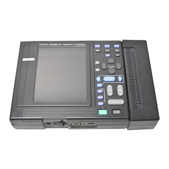
Quick Start Manual 1.1 Identification of Controls and Indicators 1.1 Identification of Controls and Indicators Front Panel This is the 8420-51. - Page 9 1.1 Identification of Controls and Indicators Buttons Operations Displays the Status Screen. Displays the Channel Screen. Displays the Waveform Screen, and selects the dis- play format of the Waveform Screen. Prints measurement data stored in memory; while measuring, starts and stops real-time printing. Prints the screen (or creates a screen image file);...
- Page 10 Quick Start Manual 1.1 Identification of Controls and Indicators Upper Upper Panel Pulse Probe Connector (PULSE) PC Card Slot Eject button These are the pulse input ter- A PC Card can be Pressing this button minals, for connecting the inserted here. ejects the PC Card.
- Page 11 1.1 Identification of Controls and Indicators Right Panel Analog Input Terminal Block These are the analog input terminals. The 8420-51 has 8 input channels, the 8421-51 has 16 input channels, and the 8422-51 has 32 input channels. Bottom Panel Battery Compartment...
- Page 12 Quick Start Manual 1.1 Identification of Controls and Indicators...
-
Page 13: Display Screen And Setting Items
2.1 Status Screen Display Screen and Setting Items This chapter describes the major screens of the Memory HiLogger and parameters to be set on each screen. 2.1 Status Screen Set the recording interval. ❖ See Section 4.2. Enter the title comment. ❖... -
Page 14: Channel Screen
Quick Start Manual 2.2 Channel Screen 2.2 Channel Screen Enter an input channel The settings can be copied Set the waveform dis- comment. from another channel. play area (range.) ❖ ❖ See Section 5.1. See Section 5.1. ❖ See Section 5.1.5. ❖... -
Page 15: Waveform Screen
2.3 Waveform Screen 2.3 Waveform Screen Display Marks ❖ Sets the digital filter. See Section 4.7. ❖ Switch the waveform display See Section 6.2. screen. This is also possible with button. Shows the wave sheet of the wave- ❖ See Section 5.1.9. form being displayed. - Page 16 Quick Start Manual 2.3 Waveform Screen...
-
Page 17: Measurement Examples
3.1 Voltage Measurement Measurement Examples 3.1 Voltage Measurement In the explanation below, we measure AC voltage fluctua- tions for a one-week period using an AC transducer (0~10 VDC rms value output for 0~150 VAC) as an example. Moni- tor voltage fluctuations for a one-week period by measuring the output voltage every minute. - Page 18 Quick Start Manual 3.1 Voltage Measurement Settings <Status Screen> Interval : 1min Time/DIV : 1h/DIV Record Time : 7 d Store CH : CH1 Auto Save : Binary (Real) File Name : AUTO (default) Save Mode : Normal Full Digital Filter : 60 Hz <Analog Channel Screen>...
- Page 19 3.1 Voltage Measurement • To avoid the danger of electric shock, never connect the power line to which the measurement cable is connected to this unit while the power line is live. • Never apply more than 30 Vrms AC or 60 VDC between ana- log inputs, or between analog inputs and chassis ground.
- Page 20 1 on the terminal board. Be sure that the polarity of the cable connection is correct. See Section 2.2 "Connecting Measurement Cables" (page 25) of Instruction Manual. Channel Number 8420-51 8422-51 8421-51 Recommended Lead Wire Single-conductor: 0.14 to 1.5 Single-conductor Stranded wire: 0.14 to 1 mm...
- Page 21 3.1 Voltage Measurement Display the Status Screen. Display the Status Screen. Set the recording interval to "1minute." Move the blinking cursor to the position shown. Select " ." 1min The setting becomes effective immediately after being selected. Close the list of settings. Set the time axis (Time/DIV) to "1h/DIV."...
- Page 22 Quick Start Manual 3.1 Voltage Measurement Set the recording period (Record Time) to "7 days." Move the blinking cursor to the position shown. Select " ." To set an arbitrary recording period, choose "OFF" for "Continuous" and then set the desired time. Turn on the channel 1 (CH1) of the Store CH.
- Page 23 3.1 Voltage Measurement Set the automatic saving to "Binary (Real time)." Move the blinking cursor to the position shown. Select " ." Binary (Real) If a file name has already been entered, the file is automatically saved with that name. For continuous saving, a number is appended to the file name.
- Page 24 Quick Start Manual 3.1 Voltage Measurement Set the digital filter to "60 Hz." Move the blinking cursor to the position shown. Select " ." 60 Hz A digital filter can be used on analog channels to remove noise in the input signals. The longer the recording interval is, the larger the noise reduc- tion effect becomes;...
- Page 25 3.1 Voltage Measurement Set the display area to "Posn&Zoom." Move the blinking cursor to the position shown. Select " ." Posn&Zoom Set the input type (Mode) to "Voltage." Move the blinking cursor to the position shown. Select " ." Volt Set the range to "10Vf.s.."...
- Page 26 Quick Start Manual 3.1 Voltage Measurement Set the display position to "0%." Move the blinking cursor to the position shown. Select " ." Set the scaling. Move the blinking cursor to the position shown. Set the display format to " ."...
- Page 27 3.1 Voltage Measurement Move the blinking cursor to the position shown. Set the scaling unit to " ." Move the blinking cursor to the position shown. Enter the following: A: +0.0000E+00 → +0.0000E+00 B: +1.0000E+01 → +1.5000E+02 ❖ See Section 5.4 "Setting Scaling" (page 86) of Instruction Manual. Upper limit value: 150 V, Lower limit value: 0 V •...
- Page 28 Quick Start Manual 3.1 Voltage Measurement Press the key to start measurement. The Waveform Screen is displayed. Press the key twice to abandon measurement while it is in progress. Measurement ends when seven days has elapsed.
-
Page 29: Temperature Measurement Using A Thermocouple (K)
3.2 Temperature Measurement Using a Thermocouple (K) 3.2 Temperature Measurement Using a Ther- mocouple (K) Measure indoor temperature changes using a thermocouple. Observe temperature changes by mea- suring the temperature every second. Settings: Temperature is input to Channel 1. Recording interval: 1 sec., Time axis: 1 min., Recording period: Continuous Data is viewed on the screen of the Memory HiLogger after measurement is complete. - Page 30 Quick Start Manual 3.2 Temperature Measurement Using a Thermocouple (K) Settings <Status Screen> Interval : 1s Time/DIV : 1min/DIV Record Time : Continuous Store CH : CH1 Auto Save : OFF Digital Filter : 60 Hz <Analog Channel Screen> Display Area : Posn&Zoom Mode : Thermocouple...
- Page 31 3.2 Temperature Measurement Using a Thermocouple (K) To avoid the danger of electric shock, never connect the power line to which the thermocouple is connected to this unit while the power line is live. Make sure the instrument is OFF. Connect the AC adapter to the instrument.
- Page 32 Using the supplied flat blade screwdriver, connect the thermocouple (K) to channel 1 on the terminal board. Be sure that the polarity of the cable connection is correct. See Section 2.2 "Connecting Measurement Cables" (page 25) of Instruction Manual. Channel Number 8420-51 8422-51 8421-51 Recommended Lead Wire Wire diameter : 0.32 mm...
- Page 33 3.2 Temperature Measurement Using a Thermocouple (K) Display the Status Screen. Display the Status Screen. Set the recording interval to "1s." Move the blinking cursor to the position shown. Select " ." The setting becomes effective immediately after being selected. Close the list of settings.
- Page 34 Quick Start Manual 3.2 Temperature Measurement Using a Thermocouple (K) Set the recording period (Record Time) to "Cont: ON." Move the blinking cursor to the position shown. Select " ." Cont: ON Turn on the channel 1 (CH1) of the Store CH. Move the blinking cursor to the position shown.
- Page 35 3.2 Temperature Measurement Using a Thermocouple (K) Display the Analog Channel Screen. Display the Analog Channel Screen for channel 1. Set the display area to "Posn&Zoom." Move the blinking cursor to the position shown. Select " ." Posn&Zoom Set the input type (Mode) to "TC (Thermocouple)." Move the blinking cursor to the position shown.
- Page 36 Quick Start Manual 3.2 Temperature Measurement Using a Thermocouple (K) Set the range to "100 f.s.." °C Move the blinking cursor to the position shown. Select " ." °C f.s. Set the thermocouple type (Sensor) to "K." Move the blinking cursor to the position shown. Select "...
- Page 37 3.2 Temperature Measurement Using a Thermocouple (K) Set the burn out detection (Burn Out) to "OFF." Move the blinking cursor to the position shown. Select " ." Set the display position to "0%." Move the blinking cursor to the position shown. Select "...
-
Page 38: Integrating The Pulse Output From A Power Meter
Quick Start Manual 3.3 Integrating the Pulse Output from a Power Meter 3.3 Integrating the Pulse Output from a Power Meter Prepare a watt-hour meter capable of outputting 50,000 pulses/kWh pulse and capture pulses from the meter to measure the integrated watt-hour for a one-month (30- day) period. - Page 39 3.3 Integrating the Pulse Output from a Power Meter Settings <Status Screen> Interval : 30min Time/DIV : 1d/DIV Record Time : 30 d Store CH : P1 Auto Save : Binary (Real) File Name : AUTO (default) Save Mode : Normal Full Digital Filter : OFF <Pulse Channel Screen>...
- Page 40 Quick Start Manual 3.3 Integrating the Pulse Output from a Power Meter To avoid the danger of electric shock, never connect the power line to which the measurement cable is connected to this unit while the power line is live. Make sure the instrument is OFF.
- Page 41 3.3 Integrating the Pulse Output from a Power Meter Connect the 9641 CONNECTION CABLE to this instrument. The 9461 CONNECTION CABLE is terminated as follows. P1 White (H) Ends of the 9641 CONNECTION CABLE P1 Red (L) P2 Yellow (H) P2 Black (L) P3 Green (H) P3 Blue (L)
- Page 42 Quick Start Manual 3.3 Integrating the Pulse Output from a Power Meter Display the Status Screen. Display the Status Screen. Set the recording interval to " ." 30min Move the blinking cursor to the position shown. Select " 30min The setting becomes effective immediately after being selected. Close the list of settings.
- Page 43 3.3 Integrating the Pulse Output from a Power Meter Set the recording period (Record Time) to "30 days." Move the blinking cursor to the position shown. Select " ." 30 d Turn on the pulse channel 1 (P1) of the Store CH. Move the blinking cursor to the position shown.
- Page 44 Quick Start Manual 3.3 Integrating the Pulse Output from a Power Meter Set the saving mode to "Normal" and "Full." Move the blinking cursor to the position shown. Select " ." Normal Move the blinking cursor to the position shown. Select "...
- Page 45 3.3 Integrating the Pulse Output from a Power Meter Set the display area to "Posn&Zoom." Move the blinking cursor to the position shown. Select " ." Posn&Zoom Set the input type (Mode) to "Count." Move the blinking cursor to the position shown. Select "...
- Page 46 Quick Start Manual 3.3 Integrating the Pulse Output from a Power Meter Set the count mode to "Add." Move the blinking cursor to the position shown. Select " ." Set the slope type to "Up." Move the blinking cursor to the position shown. Select "...
- Page 47 3.3 Integrating the Pulse Output from a Power Meter Set the filter to "ON." Move the blinking cursor to the position shown. Select " ." When a mechanical contact output device is connected to the Memory HiLogger, turn the filter to " ."...
- Page 48 Quick Start Manual 3.3 Integrating the Pulse Output from a Power Meter Set the scaling. Move the blinking cursor to the position shown. Set the display format to " ." Move the blinking cursor to the position shown. Set the scaling method to " ."...
- Page 49 3.3 Integrating the Pulse Output from a Power Meter Press the key to start measurement. Press the key twice to abandon measurement while it is in progress. Measurement ends when a month has elapsed.
- Page 50 Quick Start Manual 3.3 Integrating the Pulse Output from a Power Meter...
- Page 51 HIOKI 8420-51, 8421-51, 8422-51 MEMORY HiLOGGER Quick Start Manual Publication date: February 2004 Edition 1 Edited and published by HIOKI E.E. CORPORATION Technical Support Section All inquiries to International Sales and Marketing Department 81 Koizumi, Ueda, Nagano, 386-1192, Japan TEL: +81-268-28-0562 / FAX: +81-268-28-0568 E-mail: os-com@hioki.co.jp...
- Page 52 HEAD OFFICE 81 Koizumi, Ueda, Nagano 386-1192, Japan TEL +81-268-28-0562 / FAX +81-268-28-0568 E-mail: os-com@hioki.co.jp / URL http://www.hioki.co.jp/ HIOKI USA CORPORATION 6 Corporate Drive, Cranbury, NJ 08512, USA TEL +1-609-409-9109 / FAX +1-609-409-9108 8420E983-00 04-02H Printed on recycled paper...
Need help?
Do you have a question about the 8420-51 and is the answer not in the manual?
Questions and answers