Table of Contents
Advertisement
Quick Links
Download this manual
See also:
Instruction Manual
Advertisement
Table of Contents

Related Manuals for Hioki 8861


Summary of Contents for Hioki 8861
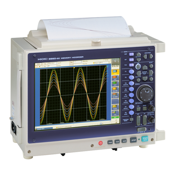
- Page 1 QUICK START MANUAL 8860 8861 MEMORY HiCORDER Read This Manual First It describes preparations for use, basic operating procedures and usage methods.
-
Page 3: Table Of Contents
Contents Contents Introduction.................1 Confirming Package Contents............2 Safety Information ..............3 Operating Precautions..............5 Chapter 1 Overview __________________________________ 11 Product Overview and Features ........11 Measurement Workflow ............ 12 Chapter 2 Names and Functions of Parts ________________ 19 Panel Names and Functions ..........19 Screen Types and Contents ..........23 Basic Operations ............... - Page 4 Contents Recording Simple Waveforms .......... 51 Actual Measurement and Analysis ........54 Chapter 5 Saving & Loading Data ______________________ 65 Recording (Storage) Media ..........66 Using PC Cards ..............67 Data that can be Saved & Loaded ........68 Saving Procedures and Contents ........70 Data Saving ..............
-
Page 5: Introduction
To obtain maximum performance from the instrument, please read this manual carefully, and keep it handy for future reference. In this document, the “instrument” means the Model 8860 or 8861 Memory HiCorder. The following documents are provided with this instrument. Refer to them as appropriate for your application. -
Page 6: Confirming Package Contents
If damage is evident, or if it fails to operate according to the specifications, contact your dealer or Hioki representative. Confirm that these contents are provided. This instrument: Model 8860/ 8861 Memory Power Cord ..........1 HiCorder (8860: 4-module, 8861: 8-module) Input Cable Labels........1... -
Page 7: Safety Information
Safety Information Safety Information This instrument is designed to comply with IEC 61010 Safety Standards, and has been thoroughly tested for safety prior to shipment. However, mis- handling during use could result in injury or death, as well as damage to the instrument. - Page 8 Safety Information Other Symbols Symbols in text Mouse operation terminology Click: Press and quickly release the left button of the Indicates the prohibited action. mouse. Right-click: Press and quickly release the right button of (⇒ p. ) Indicates the location of reference informa- the mouse.
-
Page 9: Operating Precautions
Using the instrument in such conditions could cause an electric shock, so contact your dealer or Hioki representative for replacements. Instrument Installation Operating temperature and humidity: 0 to 40°C at 20 to 80% RH (non-conden- sating) However, the operating temperature range may depend on the options used. - Page 10 • Do not allow the instrument to get wet, and do not take measurements with wet hands. This may cause an electric shock. • Never modify the instrument. Only Hioki service engineers should disas- semble or repair the instrument. Failure to observe these precautions may result in fire, electric shock, or injury.
- Page 11 Operating Precautions Before Connecting Before turning power on • Before turning the instrument on, make sure the supply voltage matches that indicated on the its power connector. Connection to an improper supply voltage may damage the instrument and present an electrical haz- ard.
- Page 12 Operating Precautions Input and Measurement Precautions The maximum input voltage and maximum rated voltage to ground (between the grounds of the input terminals and the instrument, and between inputs of other analog modules) of each input module and exter- nal input terminals are shown below. To avoid risk of electric shock and damage to the instrument, be careful to not exceed these ratings.
- Page 13 • If the optional printer module is installed, remove the paper. If the paper is left in the instrument, the paper-handling components may be damaged by vibra- tion. The optional Model 9723 and 9724 Carrying Cases are available for shipping the Models 8860 and 8861, respectively.
- Page 14 Operating Precautions...
-
Page 15: Chapter 1 Overview
Instruction Manual Memory capacity can be expanded with optional mem- ory boards. (This option must be specified when order- Recording various analog ing.) 8860: 32 Megawords to 1 Gigaword, Model 8861: signals 64 Megawords to 2 Gigawords Measurements are... -
Page 16: Measurement Workflow
1.2 Measurement Workflow 1.2 Measurement Workflow Overall workflow and summary Connect the instrument to the measurement object, and Install & Connect turn power on. ⇒ "Chapter 3 Measurement Preparations" ( p. 37) in this manual ⇒ Install the instrument "Instrument Installation" ( p. - Page 17 1.2 Measurement Workflow Operation Overview: Recording Analog Waveforms For more details, refer to "3.1 Measurement Workflow" in the Instruction Manual. Also refer to "Appendix 2 Overview of Settings and Functions" (⇒ p. A2) and "Appendix 3 Common Ques- tions" (⇒ p. A7). Installation &...
- Page 18 1.2 Measurement Workflow Input Channel Settings Make settings on the Channel Settings screen. Press the SUB MENU keys to select the menu Press the SHEET/PAGE keys to select the [One Ch] page Select the Unit (module) and Channel Select the measurement range (vertical axis) Make input-module-related settings Perform zero adjustment "Chapter 5 Input Channel Settings"...
- Page 19 1.2 Measurement Workflow Display Sheet Settings (If you want to change the layout of the waveform screen to show any combination of channels) Press the SUB MENU keys to select the Set on the Sheet Settings screen. menu (As occasion demands) Select the Screen Layout Set the number screen divisions and the split-screen layout...
- Page 20 1.2 Measurement Workflow Printing Settings (If you want to print data) Set on the Print Settings screen. Press the SUB MENU keys to select the menu Press the SHEET/PAGE keys to select the [Printer] page Select automatic or manual printing Verify that the paper is Default setting: loaded correctly.
- Page 21 1.2 Measurement Workflow Operation Overview: Recording Logic Waveforms Installation & Connections Connect the logic probes (⇒ p. 37). Refer to the Input Module Guide for details about probes. Power On Measurement Configuration Settings Make settings on the Status Settings screen. Press the key.
- Page 22 1.2 Measurement Workflow Trigger Settings (If you want to record a specific waveform, such as an anomaly) Press the SUB MENU keys to select the Make settings on the [Logic] page of the Trigger menu Settings screen. Press the SHEET/PAGE keys to select the [Logic] page...
-
Page 23: Names And Functions Of Parts
Refer to "Chapter 2 Operating Keys and Screen Contents" in the Instruction Manual for details of operating keys and screens. 2.1 Panel Names and Functions The number of installable input modules and the position of the handle differs on the Models 8860 and 8861 (Example: 8860) Front Panel... - Page 24 2.1 Panel Names and Functions Left Side Vent Handle Use to carry the instrument. (The Model 8861 has its handle on the side) Serial Number MAC Address This is required for network manage- ment, so do not peel it off.
- Page 25 2.1 Panel Names and Functions Operating Keys This section provides an overview of the operating keys. Refer to "Chapter 2 Operating Keys and Screen Contents" in the Instruction Manual for functional details of each key. Selects menus Select the Sheet (Waveform screen) or SUB MENU keys Page (Settings screen) View waveforms...
- Page 26 2.1 Panel Names and Functions Connectors SYNC. OUT Jack Use to synchronize sampling with multiple instruments. ref (Sample synchronizing signal output) "14.2.4 Synchronized Sampling Output (SYNC.OUT)" in the Instruction Manual EXT SMPL Jack Sampling can be synchronized by an external signal applied here. (External Sampling) (Memory function only) "14.2.3 External Sampling (EXT.SMPL)"...
-
Page 27: Screen Types And Contents
2.2 Screen Types and Contents 2.2 Screen Types and Contents There are five general screen types. Refer to the Instruction Manual for details about each screen type. Refer to the Analysis Supplement for details of the FFT function. At power on, either the Opening screen or the Screen with the same settings that were in effect when power was last turned off appears. - Page 28 2.2 Screen Types and Contents Press the key. Settings Screen For details of screen contents: "2.5 Settings Screen" in the Instruction Manual Displays screens for making various operation-related settings such as for measurement, data saving, printing and calculations. Select the particular settings screen from the Settings menu. Settings menu contents are function-dependent.
- Page 29 2.2 Screen Types and Contents Analysis Settings (Utility Functions) (Memory function only) Settings Menu SUB MENU SUB MENU Press the keys to select a Settings screen. (function-dependent) Memory Division (Mem Div) Numerical Calculation (Num Calc) Settings Screen Settings Screen These settings control memory partitioning. These are the display settings for numerical calcu- lations.
- Page 30 2.2 Screen Types and Contents Data Saving and Printing Settings Settings Menu SUB MENU Press the keys to select a Settings screen. SUB MENU Page SHEET/PAGE Press the keys to select a page. Save Settings Screen Print Settings Screen ([Auto Save] [SAVE Key] pages) ([Printer]...
- Page 31 2.2 Screen Types and Contents Press the [System] key on the Opening screen, or hold the key down. System Screen For screen details: "2.7 System Screen" in the Instruction Manual Use this screen to make system-related settings. Select from the menu to display a settings screen. Settings Menu Page SUB MENU...
- Page 32 2.2 Screen Types and Contents For screen details: "2.7 System Screen" in the Instruction Manual Use this screen to make system-related settings. Select from the menu to display a settings screen. Settings Menu SUB MENU SUB MENU Press the keys to select a Settings screen. Initialization (Init) Settings Screen Configuration (Config) List Screen Use this screen to set the clock, initialize data, run...
- Page 33 2.2 Screen Types and Contents Function Selection Select a function according to the desired recording data. Select from the Opening, Waveform or Set- tings screens. For function details, refer to "4.1 Selecting the Function" in the Instruction Manual Memory Function (MEM) FFT Function (FFT) System Settings This function is most suitable for...
- Page 34 2.2 Screen Types and Contents Viewing Recording Data (Waveform Screen) A/B Cursor Values Appear when the A/B cur- Trigger Mark sors are displayed. Numeri- The trigger mark appears cal calculation results and at the point where a trigger channel information can be is applied.
- Page 35 2.2 Screen Types and Contents Setting Items and Contents (Waveform Screen) Indicates current settings. These can be changed while measuring. To change a setting, use the CURSOR keys to move the cursor to it, and press an F key to choose the new value.
-
Page 36: Basic Operations
2.3 Basic Operations 2.3 Basic Operations 2.3.1 To Change Settings You have two ways to change settings. This document describes how to change settings using the F keys. In addition to the operating keys, operations can be performed using a mouse or keyboard. -
Page 37: Entering Text And Numbers
2.3 Basic Operations 2.3.2 Entering Text and Numbers "3.3.3 Entering Text and Numbers" in the Instruction Manual Entering Numbers Move the cursor to a setting item and select an input method with the F keys. When using a mouse, double click on a setting item to display the virtual keypad. Direct entry by F keys [↑↑] [↓↓] [↑] [↓] Enter a numerical value using the settings (↑↑, ↓↓, ↑... - Page 38 2.3 Basic Operations Entering Text Move the cursor to a setting item and select an input method with the F keys. When using a mouse, double click on a setting item to display the virtual key- board. "5.2 Adding Comments"; "Comment Entry Example" in the Instruction Manual Enter by virtual keyboard [Edit] Enter text using the virtual keyboard for character entry.
-
Page 39: Viewing Recorded Data
2.3 Basic Operations 2.3.3 Viewing Recorded Data Press the DISP key. The recorded waveform appears on the Waveform screen. For analysis procedures, refer to "9. Analyze Data" (⇒ p. 61), or "Chapter 8 Waveform Screen Monitoring and Analysis" in the Instruction Manual. - Page 40 2.3 Basic Operations...
-
Page 41: Measurement Preparations
3.1 Installation & Connection Procedures Measurement Chapter 3 Preparations 3.1 Installation & Connection Procedures ⇒ Be sure to read the "Operating Precautions" ( p. 5) before installing and connecting this instrument. (When adding or changing an input module) Install this instrument Install an input module ⇒... -
Page 42: Connecting Cables And Probes
Connection Preparations • Do not use cables other than those specified by Hioki. The specified cables use insulated BNC connectors to avoid electric shock accidents. An uninsulated BNC plug may cause electric shock or damage to the BNC jack. - Page 43 3.2 Connecting Cables and Probes Measuring Voltage Applicable Input Modules Use to connect: Connection Cables • Model 8956 Analog Unit • Model 8936 Analog Unit • Model 9197 Connection Cord • Model 8938 FFT Analog Unit (Maximum input voltage: 500 V) Large alligator clip type •...
- Page 44 Use to connect: Sensor Applicable Input Modules • Model 8939 Strain Unit Strain Gauge Transducer • Model 8960 Strain Unit (Not available from Hioki) Connect to the BNC jack on an input mod- Example: ule. Connecting using a conver- Connection Procedure: sion cable "2.2.4 Connecting to a Strain Unit (Models...
- Page 45 Voltage Measurement: Model 9198 Connection Cord Connect to the miniature receptacle on the (recommended) input module. Connection Procedure: * Not available from Hioki "2.2.6 Connecting to the Model 8947 Charge Unit" in the Input Module Guide Measuring Logic Signals Connection Procedure: Use to connect: Logic Probe "2.6 Connecting Logic Probes"...
-
Page 46: Loading Recording Paper (With A Printer Module Installed)
3.3 Loading Recording Paper (With a Printer Module Installed) 3.3 Loading Recording Paper (With a Printer Module Installed) Printing is available using the following optional printer (specified when ordering the instrument) and recording paper. Printer Recording Paper (size) Model 8995 A4 Printer Unit Model 9231 Recording Paper (A4 size) Model 8995-01 A6 Printer Unit Model 9234 Recording Paper (A6 size) - Page 47 3.3 Loading Recording Paper (With a Printer Module Installed) Loading Recording Paper in the Model 8995 A4 Printer Unit Stock Cover Pull the knob to open the stock cover. Knob Head-Raising Lever Pull the head-raising lever forward. The print head is separated from the print roller. (Head-raised condition) Print Roller Put the paper roll holders in the ends of the...
- Page 48 3.3 Loading Recording Paper (With a Printer Module Installed) Loading Recording Paper in the Model 8995-01 A6 Printer Unit Stock Cover Push the stock cover to open the stock cover. Head-Raising Lever Raise the head-raising lever. The print head is separated from the print roller. (Head-raised condition) Print Roller Back Side of...
-
Page 49: Connecting The Power Cord
3.4 Connecting the Power Cord 3.4 Connecting the Power Cord • Before turning the instrument on, make sure the supply voltage matches that indicated on the its power connector. Connection to an improper supply voltage may damage the instrument and present an electrical haz- ard. -
Page 50: Turning The Power On And Off
3.6 Turning the Power On and Off 3.6 Turning the Power On and Off Turning Power On Before turning Verify that the instrument and peripheral devices are correctly connected. power on Left Side Turn the POWER switch on ( | ). After Power-On After a short time, the STANDBY/ON... - Page 51 3.6 Turning the Power On and Off To Avoid the Startup Delay (Entering the Standby State) Press the STANDBY/ON key. “Enter Standby Mode?” appears. Press the STANDBY/ON key again. (It slowly blinks red) The screen turns off and the instrument enters the standby state.
-
Page 52: Setting The Clock
3.7 Setting the Clock 3.7 Setting the Clock To adjust the clock, set the date and time on the Initialization screen of the Sys- tem screen. If you need to change both the time zone and the date and time, change the time zone first. -
Page 53: Chapter 4 Basic Operations
4.1 Pre-Measurement Inspection Before using the instrument the first time, verify that it operates normally to ensure that the no damage occurred during storage or shipping. If you find any damage, contact your dealer or Hioki representative. Peripheral Device Inspection... -
Page 54: Operation Workflow
4.2 Operation Workflow 4.2 Operation Workflow Installation & Connections Turn Power On ⇒ "Chapter 3 Measurement Preparations" ( p. 37) Settings Measure with New Settings Measure with Existing Settings FILE Select a Function Settings Screen Range can be set auto- File Screen ⇒... -
Page 55: Recording Simple Waveforms
4.3 Recording Simple Waveforms 4.3 Recording Simple Waveforms First display the waveform for confirmation. This description presumes that settings are at their factory default values. If the instrument has been used before, or if you suspect that settings are not at their factory default values, reinitialize the instrument before proceeding. - Page 56 4.3 Recording Simple Waveforms Set Up the Instrument (Auto Setup) Press the FUNCTION MODE to enable the FN mode. Press the F4 [Auto Setup] key. A confirmation message appears. Press the F1 [OK] key. The timebase, measurement range and zero position are automatically set, and recording starts.
- Page 57 4.3 Recording Simple Waveforms To Change Settings Changing the timebase or recording length Use the CURSOR keys to move the cursor to the set- ting item, and press to select the setting val- Setting Items ue. Pressing the SUB MENU keys changes available setting items.
-
Page 58: Actual Measurement And Analysis
4.4 Actual Measurement and Analysis 4.4 Actual Measurement and Analysis This example uses an analog input module and connection cable to illustrate the basic measurement process of recording and analyzing an anomalous waveform. Settings and measurement procedures differ according to the specific application, as described in the Input Module Guide, the Instruction Manual and the Analysis Supplement . - Page 59 4.4 Actual Measurement and Analysis Measurement Preparations ⇒ "Chapter 3 Measurement Preparations" ( p. 37), and "Chapter 2 Connections" in the Input Module Guide Connect the power cord from Connect the cable to a BNC jack this instrument to an outlet. on the Model 8936 Analog Unit.
- Page 60 4.4 Actual Measurement and Analysis Select the appropriate function ⇒ "Function Selection" ( p. 29) Opening Screen Case Press the F1 [MEM] (Memory Function) key. Function Menu Waveform or Setting Screen Case Using the CURSOR keys, move the cursor to the Function menu, and press the F1 [MEM] key.
-
Page 61: Chapter 5
4.4 Actual Measurement and Analysis Set up the input channel "Chapter 5 Input Channel Settings" in the Instruction Manual and "Chapter 3 Input Channel Settings" in the Input Module Guide Press the SUB MENU keys to select the [Channel] menu item. Now use the keys to move CURSOR... - Page 62 4.4 Actual Measurement and Analysis Set Trigger Criteria "Chapter 6 Trigger Settings" in the Instruction Manual Press the SUB MENU keys to select the [Trigger] menu item. Now use the CURSOR keys to move among the setting items, and press the keys to select the desired setting.
- Page 63 4.4 Actual Measurement and Analysis Enable Auto-Save "Chapter 10 Saving/Loading Data & Managing Files" in the Instruction Manual Press the SUB MENU keys to select the [Save] menu item. Press the SHEET/PAGE keys to Now use the CURSOR keys to move select the [Auto Save] page.
- Page 64 4.4 Actual Measurement and Analysis Start Measurement "3.3.6 Starting and Stopping Measurement" in the Instruction Manual Press the START key. The green LED lights, and the Waveform screen appears. The instrument’s measurement status is displayed on the Status bar. Status Bar Display Trigger Wait Recording does not occur until the specified trigger criteria are met.
- Page 65 4.4 Actual Measurement and Analysis Analyze Data "Chapter 8 Waveform Screen Monitoring and Analysis" in the Instruction Manual Trigger Event Position Displayed Channel Time from Trigger Event Number of Waveform Trigger Event Time Name of Currently Displayed Sheet Acquisitions What about these situations? To measure with changed set- After changing settings on the Waveform or Settings screen, press the START...
- Page 66 4.4 Actual Measurement and Analysis Viewing the Whole Waveform Select the [Mag] (Magnification) button "8.9 Magnifying and Compressing Waveforms" in the Instruction Manual Using the CURSOR keys, move the cursor to [Mag], and press the F1 [Whole Wave] key. The whole waveform over the specified recording length is displayed.
- Page 67 4.4 Actual Measurement and Analysis Viewing Measurement Values Use the A/B cursors "8.8 Cursor Values" in the Instruction Manual Knob A Knob B Press the TYPE key to select the cursor type. The [A/B Cursor] dialog appears. • To view the time and voltage (measurement) value: Dialog [Trace] •...
- Page 68 4.4 Actual Measurement and Analysis Printing a Selected Waveform Section "Chapter 11 Printing" in the Instruction Manual This procedure describes Selection Printing (default setting). Specify the section to print using the vertical or trace cursors. ⇒ See"Viewing Measurement Values" ( p.
-
Page 69: Chapter 5 Saving & Loading Data
Saving & Loading Chapter 5 Data The default at shipping and initialization of this setting is [Selection Save]. To save selections, press the SAVE key, make the appropriate settings and save them. You can later change your saved settings from the Save Settings screen as occasion demands. -
Page 70: Recording (Storage) Media
5.1 Recording (Storage) Media 5.1 Recording (Storage) Media Storage Media Designation Storage Media Remarks and Hioki Options (when specifying the storage media type) (Built-in slots provided) • Model 9626 PC CARD 32M • Model 9627 PC CARD 64M • Model 9726 PC CARD 128M... -
Page 71: Using Pc Cards
5.2 Using PC Cards Important Use only PC Cards sold by Hioki (⇒ p. 66). Compatibility and performance are not guaranteed for PC cards made by other manufacturers. You may be unable to read from or save data to such cards. -
Page 72: Data That Can Be Saved & Loaded
5.3 Data that can be Saved & Loaded 5.3 Data that can be Saved & Loaded The following data can be saved and loaded with this instrument. Auto Save saves the data automatically after measurement. “O” = Possible, “–” = Not Possible Save File File Type... - Page 73 5.3 Data that can be Saved & Loaded *1. Settings data can be loaded automatically at power-on. (Auto Setup Function) *2. To reload data into this instrument: Save it in binary format. Waveforms and some of the measurement settings are saved. To load data into a PC: Save it in text format.
-
Page 74: Saving Procedures And Contents
5.4 Saving Procedures and Contents 5.4 Saving Procedures and Contents Basically, three methods are available for saving. To save automatically while To save immediately upon To save selected contents measuring pressing the SAVE Auto Save Quick Save Selection Save Automatically saves all acquired This method is convenient for saving (Default setting) measurement data for the specified... -
Page 75: Data Saving
5.5 Data Saving 5.5 Data Saving The saving procedure for various data items using the default [Selection Save] method is described here. Available setting contents are the same for the [Quick Save] method. Refer to "6. Enable Auto-Save" (⇒ p. 59) for more details about Auto Save. Refer to "10.3 Saving Data"... - Page 76 5.5 Data Saving Saving Waveforms "10.3.8 Optionally Selecting Waveforms & Saving (SAVE Key)" in the Instruction Manual Use the CURSOR keys to move the cursor to the "Shared Settings in Selection Save" (⇒ p. 71) setting item, and select the desired setting contents with the key.
- Page 77 5.5 Data Saving Saving Settings Data "10.3.6 Saving Settings Data" in the Instruction Manual "Shared Settings in Selection Save" (⇒ p. 71) Use the CURSOR keys to move the cursor to the setting item, and select the desired setting contents with the key.
-
Page 78: Data Loading
5.6 Data Loading 5.6 Data Loading Settings Data Waveform Data Verify before loading • Is storage media inserted? Insert storage media Insert storage media • Is the loading source correct? This instrument can load data saved Select the data to load Select the data to load in binary format. -
Page 79: Chapter 6 Printing
Chapter 6 Printing The shipping and initial default printing method is [Selection Print]. With this setting, printing occurs after pressing the PRINT key and selecting what you want to print. You can change print settings as occasion demands from the Print Settings screen. Refer to "Chapter 11 Printing"... -
Page 80: Printing Methods And Contents
6.1 Printing Methods and Contents 6.1 Printing Methods and Contents Basically, three printing methods are available. To print automatically while To print immediately upon To select and print specified measuring pressing the PRINT items after measuring Selection Print Auto Print Quick Print (Default setting) With the Memory Function*, prints au-... -
Page 81: Printing While Recording (Auto Print)
6.2 Printing While Recording (Auto Print) 6.2 Printing While Recording (Auto Print) Enable Auto Print "11.3 Making Auto Print Settings" in the Instruction Manual Press the SUB MENU keys to select the [Print] menu. Press the SHEET/PAGE keys Now use the CURSOR keys to move among the to select the... -
Page 82: Manual Printing (Print Key)
6.3 Manual Printing (PRINT Key) 6.3 Manual Printing (PRINT Key) [Selection Print] method is described here. To use the [Quick Print] method, refer to "11.4 Making Manual Print (PRINT Key Output) Settings" in the Instruction Manual. Press the SUB MENU keys to select the [Print] menu. -
Page 83: To Print A Detailed Settings List
6.4 To Print a Detailed Settings List 6.4 To Print a Detailed Settings List When printing waveforms [Waveform Print Items] Setting Item Selection Description Off, Normal, Fine, Normal (Dark), Select the type and darkness of the Grid Type Fine (Dark), printed grid. - Page 84 6.4 To Print a Detailed Settings List...
-
Page 85: Maintenance And Service
Have the battery replaced if the date and time are found to lag substantially or if settings are not retained when power is turned off and back on. Contact your dealer or Hioki representative. The fuse is housed in the power unit of the instrument. If the power does not turn on, the fuse may be blown. - Page 86 7.1 Troubleshooting Disposing of the Instrument This instrument includes a lithium battery to retain settings. Remove this battery before disposing of the instrument. Also remove the optional Model 9719 Mem- ory Backup Unit, if installed. "Appendix 6 Disposing of the Instrument" in the Instruction Manual Before returning for repair If Power and Operating Keys Malfunction Symptom...
- Page 87 7.1 Troubleshooting Cannot Print, or Printing Malfunctions Symptom Check Item, or Cause Remedy and Reference Verify that the recording paper is loaded cor- Nothing prints rectly. Is the paper reversed (back to front)? paper. "3.3 Loading Recording Paper (With a ⇒...
-
Page 88: Cleaning
7.2 Cleaning 7.2 Cleaning Cleaning the Instrument and Input Modules • To clean the instrument and input modules, wipe it gently with a soft cloth moistened with water or mild detergent. Never use solvents such as benzene, alcohol, acetone, ether, ketones, thinners or gasoline, as they can deform and discolor the case. - Page 89 7.2 Cleaning Print Head Cleaning Normally, no maintenance is required. However, depending on usage conditions, dirt and paper dust may accumulate on the thermal head over the long term, causing light or smeared printing. In this case, clean the head by the following procedure.
- Page 90 7.2 Cleaning Washing the Print Head Moisten the back side of a piece of printing paper with undiluted alcohol, and insert it into the printer. If the front side is moistened, it becomes discolored. Back Side of Printing Paper Be careful not to apply too much undiluted alco- hol.
-
Page 91: Appendix 1 Waveform Screen Display & Icons
Appendix 1 Waveform Screen Display & Icons Appendix Appendix 1 Waveform Screen Display & Icons "2.4 Waveform Screen" of the Instruction Manual Internal Processing State Peripheral Device Info Setting Info Before acquiring data PC Card Auto Save (Waveforms) Pre-Trig Wait Appears only when pre-trig- No Card (Blank) -
Page 92: Appendix 2 Overview Of Settings And Functions
Appendix 2 Overview of Settings and Functions Appendix 2 Overview of Settings and Functions Instrument Settings About the Screen The instrument’s LCD provides SVGA (800 × 600) resolution. The wave- form display area consists of 625 horizontal dots and 500 vertical dots. The waveform display area is divided into 25 divisions horizontally, and 20 div 20 divisions vertically, with each division composed of 25 dots horizon-... - Page 93 Appendix 2 Overview of Settings and Functions Recording Length Setting "4.2.4 Setting the Recording Length (number of divisions)" in the Instruction Manual Set the length (number of divisions) to record each time data is acquired. Each division of the recording length consists of 100 data points.
- Page 94 Appendix 2 Overview of Settings and Functions Convenience Functions If the appropriate timebase or measurement range is unknown Auto-Ranging Function "3.3.5 Automatic Range Setting (Auto-Ranging Function)" in the Instruction Manual Automatically selects the timebase and range settings to display 1 to 2.5 waveform cycles.
- Page 95 Appendix 2 Overview of Settings and Functions To view waveform data as numerical values/ To change the waveform display format Numerical Values Display "8.13 Viewing Waveform Data as Numerical Values" of the Instruction Manual Split-Screen Display "7.2.4 Splitting the Display Screen (Split-Screen)" of the Instruction 0 ms 0.3V 5 ms...
- Page 96 Appendix 2 Overview of Settings and Functions To compare with previous waveforms Memory Division "4.3.3 Dividing Memory" of the Instruction Manual By dividing the memory space into multiple blocks, waveform data can be re- corded in any block, or overlaid with any other waveforms. 1 2 3 4 5 6 Overlay "4.3.2 Overlaying Waveforms"...
-
Page 97: Appendix 3 Common Questions
Appendix 3 Common Questions Appendix 3 Common Questions Read this when you want to perform a certain task, or when the procedure for a particular operation is unknown. Refer to "7.1 Troubleshooting" (⇒ p. 81) if the display or operation seems abnormal, or if damage is suspected. - Page 98 Appendix 3 Common Questions In this case Description Reference Use a voltage measuring input module and the Model "2.4 Connecting a Differential Probe", "2.5 Connecting Atten- 9322 Differential Probe or Model 9665 (10:1) or 9666 To observe the voltage wave- uating Probes", and "3.10.15 (100:1) attenuating probes.
- Page 99 Appendix 3 Common Questions In this case Description Reference When trigger criteria are met, recording starts and con- tinues until you press the STOP key. Up to 5,000 divi- About memory capacity and re- How long will recording con- sions of data (with Model 9715 Memory Board installed) cording length: tinue when the recording from measurements prior to the stopping of recording is...
- Page 100 Appendix 3 Common Questions In this case Description Reference “Trigger Wait” is displayed Is the time trigger enabled [On] or another trigger source even though triggering is not enabled? Verify settings on the Trigger Settings screen. enabled Is the Roll Mode function (on the Status Settings screen) "4.3.1 Displaying Waveforms “Storing”...
- Page 101 Appendix 3 Common Questions Printing In this case Description Reference To print the gauge, select [Gauge] [List & Gauge] To add or remove the gauge [List & Gauge] setting of the [Print Items] on the Print "11.6.2 Printing Waveforms" in Settings screen.
- Page 102 Appendix 3 Common Questions In this case Description Reference The Environment Settings screen of the System screen To print system setting con- can be printed as a list. Use Screen Print to print other tents screens. Data Analysis In this case Description Reference "5.3 Data that can be Saved &...
-
Page 103: Index
Index Index Index Numerics Clamps ............... 39 Clock setting ............48 100Base-TX Jack ..........22 Comment ............57 8936 Analog Unit ..........39 Connection ............37 Current measurement ........39 8937 Voltage/Temp Unit .......39, 40 Frequency, Count, or Pulse duty 8938 FFT Analog Unit .........39 measurement .......... - Page 104 Index Index FN mode ............21, 23 Maximum rated voltage to ground ......8 ..............A6 Measurement Before measurement ........ 49, 59 Function ............29, 56 End of measurement ........ 16, 60 FUNCTION MODE key ........ 21, 23 Start of measurement .......
- Page 105 Index Index PS/2 keyboard jack ..........22 Shuttle ..............21 PS/2 mouse jack ..........22 SPEED key ............21 Pull-down menu ..........21, 32 Standby .............. 47 Pushwheel ............33 STANDBY/ON key ........21, 46 START key ........... 21, 60 Status ............24, 56 Status bar ............
- Page 106 Index Index Zero adjustment ........... 14, 46 Zero position ........21, 53, 57, 79 Zero-adjust ............57 Zoom ............31, 62, A5...
- Page 109 HIOKI 8860/8861 MEMORY HiCORDER Quick Start Manual Publication date: November 2006 Revised edition 5 Edited and published by HIOKI E.E. CORPORATION Technical Support Section All inquiries to International Sales and Marketing Department 81 Koizumi, Ueda, Nagano, 386-1192, Japan TEL: +81-268-28-0562 / FAX: +81-268-28-0568 E-mail: os-com@hioki.co.jp...
- Page 110 HEAD OFFICE 81 Koizumi, Ueda, Nagano 386-1192, Japan TEL +81-268-28-0562 / FAX +81-268-28-0568 E-mail: os-com@hioki.co.jp / URL http://www.hioki.co.jp/ HIOKI USA CORPORATION 6 Corporate Drive, Cranbury, NJ 08512, USA TEL +1-609-409-9109 / FAX +1-609-409-9108 8860A981-05 06-11H Printed on recycled paper...
Need help?
Do you have a question about the 8861 and is the answer not in the manual?
Questions and answers