
Related Manuals for Hioki 8423


Summary of Contents for Hioki 8423
- Page 1 8423 Instruction Manual MEMORY HiLOGGER T h i s m a n u a l d e s c r i b e s t h e Memory HiLogger's functions and operation in detail, and its specifications. Mar. 2019 Revised edition 9...
-
Page 3: Table Of Contents
Contents Contents Introduction.................1 Verifying Package Contents ............2 Safety Information ..............4 Operating Precautions..............6 Chapter 1 Overview ________________________ 9 Product Overview ..............9 Features ................10 Names and Functions of Parts ..........12 System Configuration ............15 Measurement Flowchart ...........16 Chapter 2 Installing the Software ____________ 17 Installing Logger Utility ............18 Installing the USB Driver ...........21 Connect the instrument and computer with the USB... - Page 4 Contents 3.6.1 Formatting a CF Card ............45 3.6.2 Inserting and Ejecting a CF Card ........... 46 3.6.3 Replacing a CF Card during Measurement ......47 3.6.4 File Protection during Power Outage ........47 Connecting Synchronization Cables ......... 48 Connection Method for External Control Input Terminals . 50 Turning the Power On and Off ..........
- Page 5 Contents Setting Environment Conditions ........121 5.7.1 Setting External Control Input Terminals ......121 5.7.2 CF Card Save Settings ............123 5.7.3 Time Value Display ...............125 5.7.4 Start Backup .................126 Send Settings ..............127 Process All ..............128 5.10 Narrowing Down of Display Channels ......129 Chapter 6 Starting and Stopping Measurement131 Pre-Operation Inspection ..........134 Starting and Ending Measurement .........135...
- Page 6 Contents 8.1.3 Reading Measurement Data ..........169 Saving and Reading Setting Data ........170 8.2.1 Saving Setting Data ............. 170 8.2.2 Reading Setting Data ............170 Automatically Transferring Measurement Data to Excel . 171 8.3.1 Real-Time Transfer Settings ..........171 8.3.2 Real-Time Transfer Example ..........
- Page 7 Appendix 2 Version Update............A 2 Appendix 3 Error Display............... A 3 Appendix 3.1 Application Software ..............A 3 Appendix 3.2 8423 Memory HiLogger Main Unit ..........A 5 Appendix 4 Recording Intervals and Maximum Times for Recording to CF Cards..........A 7...
- Page 8 Contents Appendix 4.1 Model 9726 PC Card 128M ............A 8 Appendix 4.2 Model 9727 PC Card 256M ............A 10 Appendix 4.3 Model 9728 PC Card 512M ............A 12 Appendix 4.4 Model 9729 PC Card 1G ............A 14 Index ________________________________Index 1...
-
Page 9: Contents
Introduction Introduction Thank you for purchasing the HIOKI "Model 8423 Memory HiLogger." To obtain maximum performance from the instrument, please read this manual first, and keep it handy for future reference. The 8423 Memory HiLogger is a data collection instrument for use con- nected to a computer. -
Page 10: Verifying Package Contents
In particular, check the accessories, panel switches, and connectors. If damage is evident, or if it fails to operate according to the specifications, contact your dealer or Hioki representative. Please check to make sure that no items are missing from your package. - Page 11 Verifying Package Contents Options The following options are available. Model 8948 Voltage/Temp Unit Model 8949 Universal Unit Model 8996 Digital/Pulse Unit Model 8997 Alarm Unit Model 9418-15 AC Adapter Model 9642 LAN Cable Model 9701 Humidity Sensor Model 9726 PC Card 128M Model 9683 Connection Cable (for synchronization) Model 9727 PC Card 256M...
-
Page 12: Safety Information
Safety Information Safety Information This instrument is designed to comply with IEC 61010 Safety Standards, and has been thoroughly tested for safety prior to shipment. However, mis- handling during use could result in injury or death, as well as damage to the instrument. - Page 13 The maximum displayable value or scale length. This is usually the name of the currently selected range. Measurement Categories This 8423's unit complies with CAT II safety requirements. To ensure safe operation of measurement instruments, IEC 61010 establishes safety standards for various electrical environments, categorized as CAT II to CAT IV, and called measurement categories.
-
Page 14: Operating Precautions
Before using the instrument, make sure that the insulation on the cables is undamaged and that no bare conductors are improperly exposed. Using the instrument in such conditions could cause an electric shock, so con- tact your dealer or Hioki representative for replacements. Installing the Instrument Operating temperature & humidity: 0 to 40°C (32 to 104°F), 30 to 80%RH (non-condensating) - Page 15 Never modify the instrument. Only Hioki service engineers should disas- semble or repair the instrument. Failure to observe these precautions may result in fire, electric shock, or injury.
- Page 16 Never use abrasives or solvent cleaners. • Hioki shall not be held liable for any problems with a computer system that arises from the use of this CD, or for any problem related to the purchase of a...
-
Page 17: Chapter 1 Overview
Overview 1.1 Product Overview The 8423 Memory HiLogger is a computer based data collection instrument. A combination of four types of unit can be connected to enable the measurement of up to 120 channels with one Memory HiLogger. Furthermore, the synchronous operation of a maximum of five Memory HiLoggers enables you to build a sys- tem with up to 600 channels. -
Page 18: Features
Multiple Channels (Up to 600 Channels) A maximum of eight units can be connected to one 8423 Memory HiLogger to enable the measurement of up to 120 channels. Furthermore, the synchronous operation of five Memory HiLoggers facilitates the synchronized measurement of 600 channels. - Page 19 1.2 Features Synchronized Measurement Connecting multiple Memory HiLoggers with optional 9683 Connection Cable (for synchronization) allows for synchronized measurement. See "3.7 Connect- ing Synchronization Cables" (p. 48). Equipped with LAN & USB Interfaces The instrument is compatible with LAN 100BASE-TX and USB2.0. A computer and Memory HiLogger can be connected to enable the supplied software Logger Utility to be used to control the Memory HiLogger and collect data.
-
Page 20: Names And Functions Of Parts
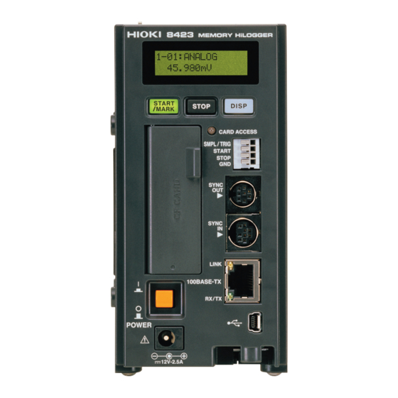
1.3 Names and Functions of Parts 1.3 Names and Functions of Parts Front Panel Key operations Display (See the next page) External control input terminals CF card access LED Synchronization cable connectors CF card slot 100BASE-TX connector Power switch USB connector AC adapter connector Names of Parts Explanations... - Page 21 1.3 Names and Functions of Parts Key Operations Keys Explanations • The key lights during measurement. • Press the key once during standby to start measurement. • Press the key during measurement to input an event mark. When the power is on: You can initialize the settings by turning the power on while pressing See "13.3 Initializing Settings (System Reset)"...
- Page 22 1.3 Names and Functions of Parts Rear Panel Wall surface mounting nut DIN Rail Mounting Groove Wall surface Wall surface mounting nut mounting nut Lever Upper/Bottom Panel Connection fittings Left Panel Right Panel Serial No. When controlling this instrument Connector Connector cover with Logger Utility, use the serial No.
-
Page 23: System Configuration
1.4 System Configuration 1.4 System Configuration The system configuration is as follows. Connection Example: External control input Model 8423 Memory HiLogger Model 9683 Con- nection Cable (for synchronization) 9642 LAN Model Cable USB cable Model 9418-15 AC Adapter Model 8948 Voltage/Temp Unit... -
Page 24: Measurement Flowchart
1.5 Measurement Flowchart 1.5 Measurement Flowchart Proceed with measurement while referring to the following measurement flowchart. Preparing for Measurement At the time Install the software on the PC (p. 18) of purchase Install and connect the instrument (p. 31) Start the software Logger Utility Setting Measurement Conditions Viewing Saved Data Register the logger in Logger Utility (p. -
Page 25: Chapter 2 Installing The Software
Installing the Chapter 2 Software Install the supplied software Logger Utility on the computer the first time you use the instrument after purchase. Before starting the installation, check the operat- ing environment. Installation Procedure (1) Set the CD into the drive of the computer Supplied CD Operating Environment (2) Install Logger Utility (p. -
Page 26: Installing Logger Utility
2.1 Installing Logger Utility 2.1 Installing Logger Utility Follow the procedure below to install Logger Utility. This explanation is for install- ing the software on Windows XP. The messages displayed may differ slightly depending on other operation system or settings you are using. Important If you are running software such as antivirus software, be sure to end the software before you start the installation. - Page 27 2.1 Installing Logger Utility Click the [Next] button of the installer, then read and agree with the con- tents in the License Agreement before clicking the [Next] button. (1) Click (2) Click (3) Click Click [Everyone] before clicking the [Next] button.
- Page 28 2.1 Installing Logger Utility Click [Next] to start installing. Click Installation starts. Progress is displayed during installation. To interrupt installation in progress, click [Cancel] Click Installation finished...
-
Page 29: Installing The Usb Driver
Install the USB driver before you use the instrument with a USB connection. Install the driver. [SetupDriver32.msi] in the CD-R. If [Logger Utility] is already installed, run the CD from the following location. [c:\Program Files\HIOKI\LoggerUtility\Driver\SetupDriver32.msi] If you are using the WindowsVista/7 64bit version: [c:\Program Files(x86)\HIOKI\LoggerUtility\Driver\SetupDriver64.msi] [SetupDriver64.msi] in the CD-R. - Page 30 2.2 Installing the USB Driver Check [Everyone] and click [Next]. (1) Check (2) Click When you want to change the installation destination, click to change [Browse…] the folder to install into. Normally, there is no need to change. Click [Next] to start installing.
- Page 31 When a dialog box requesting your permission to continue the program appears, click [Continue]. Click Sometimes another dialog box requesting your permission to install the software may appear. When it does, check [Always trust software from “HIOKI E.E. CORPORATION”] and click [Install] to continue. (2) Click (1) Check...
- Page 32 2.2 Installing the USB Driver When installation is completed and the dialog box appears, click [Close] exit. Click This completes the driver installation.
-
Page 33: Connect The Instrument And Computer With The Usb Cable Provided
2.3 Connect the instrument and computer with the USB cable provided 2.3 Connect the instrument and computer with the USB cable provided Please connect the instrument after installing the USB driver. Do not plug in or unplug the USB cable while the instrument is operating. For Windows 2000/Vista/7 Connect the AC adapter to the instrument and switch on the power. - Page 34 2.3 Connect the instrument and computer with the USB cable provided Check [Install the software automatically (Recommended)] and click [Next]. (1) Check (2) Click Please wait while the driver is being installed. A message saying that the software has not passed Windows Logo testing will appear a few times, click [Continue Anyway] to continue installing.
- Page 35 2.3 Connect the instrument and computer with the USB cable provided When installation is completed and the dialog box appears, click [Finish] to exit. Click This completes the driver installation.
-
Page 36: Starting And Ending Logger Utility
2.4 Starting and Ending Logger Utility 2.4 Starting and Ending Logger Utility Starting Logger Utility From the Start Menu of Windows, click [All Programs] - [HIOKI] - [Logger Utility] - [Logger Utility] (2) Click (1) Click Logger Utility starts with the settings in the same state as when the software was last ended. - Page 37 2.4 Starting and Ending Logger Utility Ending Logger Utility Click from the File menu of the main screen. [Exit Application] Click Alternatively, you can click the close button at the top right of the main screen. Click Close button Maximizes the Closes the Minimizes the window.
-
Page 38: Uninstalling The Logger Utility
(2) Click (3) Click [Add or Remove Programs] screen appears. (1) Click From the list of installed programs, select [HIOKI Logger Utility], and remove it. (1) Click A confirmation dialog appears when you click [Remove]. (2) Click The uninstall process begins. -
Page 39: Chapter 3 Setting Up The Instrument
Setting Up Chapter 3 the Instrument This section describes preparations for starting measurement. Before connecting the instrument to a computer or network, install Logger Utility while referring to "Chapter 2 Installing the Software" (p. 17). Installation and Connection Procedure (1) Attaching units (p. 32) (2) Connect the input cables to the units (p. -
Page 40: Attaching Units
3.1 Attaching Units 3.1 Attaching Units You can attach optional units to the instrument in accordance with the measure- ment object. A maximum of eight units (total of 120 channels) can be connected to one instrument. 3.1.1 Unit Types The following four types of unit are available. Select a unit in accordance with the measuring object. -
Page 41: Attaching A Unit
Required tools: Phillips screwdriver ....1 Turn off the power of the unit. Disconnect any connected cables. Attach the unit to the 8423 Memory HiLogger. To attach multiple units. repeat the same procedure. Left side of Memory Right side of... - Page 42 3.1 Attaching Units Attach the supplied connector cover to the unit on the very left side when looking from the front. Insert the protruding part of the connector cover into the connector opening of the unit, close the cover, and then secure it in place with the screw. Tighten the screw to no more than 0.6 Nm.
-
Page 43: Connecting A Cable To The Terminal Block
3.2 Connecting a Cable to the Terminal Block 3.2 Connecting a Cable to the Terminal Block Connect cables to the terminal block of a unit in accordance with the purpose of use. 3.2.1 Removing and Attaching a Terminal Block A terminal block can be removed to enable the cable to be easily connected. (You can also connect the cable while the terminal block is attached.) To avoid an electric shock or short-circuit accident: •... - Page 44 3.2 Connecting a Cable to the Terminal Block • Be sure to attach the removed terminal block to the unit to which it was origi- nally attached. • Since the structure of a terminal block is designed so that it cannot be attached to a unit of a different type, using excessive force to try to attach a terminal block to the wrong unit will damage the connector.
-
Page 45: Connecting A Cable
3.2 Connecting a Cable to the Terminal Block 3.2.2 Connecting a Cable To connect a cable to a terminal block, lift up the cover at the front and then con- nect the cable to the terminal block. • In order to prevent electric shock and short-circuit accidents, shut off the power to the line to be measured before connecting the input cable. - Page 46 3.2 Connecting a Cable to the Terminal Block Voltage Measurement and Temperature Measurement with Thermocouple Model 8948 Voltage/Temp Unit Model 8949 Universal Unit Not connected 4-20 mA Input Model 8948 Voltage/Temp Unit Model 8949 Universal Unit Not connected Ω shunt resistance Ω...
- Page 47 3.2 Connecting a Cable to the Terminal Block • If an input cable of 3 m or longer is connected, measurement may be affected by external noise and other electromagnetic interference. • The general guidelines for resistance temperature detector terminations are pro- vided in JIS Z 8704, in which A and B signals are designated by red and white wires, respectively.
-
Page 48: Installing The Memory Hilogger
Turn off the power of the unit. Disconnect any connected cables. Refer to the figure below and create mounting holes in the wall surface. φ φ φ Unit Unit Model 8423 23.5 21.5 17.2 17.2 19.5 Unit: mm 26.4 18.8 Insert the screws from the back side of the wall surface and secure the instrument with the nuts on the rear of the instrument. -
Page 49: Securing With A Din Rail
Secure the DIN rail to a wall or other surface. Turn off the power of the unit. Disconnect any connected cables. Pull up the levers on the rear of the instrument and unit. (The figure shows the 8423 Memory HiLogger main unit.) DIN Rail Mounting Groove Lever Hook the hooks at the top of the DIN rail mounting groove on to the DIN rail and push in the bottom. -
Page 50: Connecting The Ac Adapter
3.4 Connecting the AC Adapter 3.4 Connecting the AC Adapter This section describes connecting the 9418-15 AC Adapter to the instrument in order to supply power. • Turn the instrument off before connecting the AC adapter to the instrument and to AC power. -
Page 51: Connecting A Communication Cable
3.5 Connecting a Communication Cable 3.5 Connecting a Communication Cable A computer is used to set the instrument, record measurement data, and ana- lyze recorded data. Use the USB cable or 9642 LAN Cable to connect the instru- ment and computer. •... -
Page 52: Connecting The Lan Cable
3.5 Connecting a Communication Cable 3.5.2 Connecting the LAN Cable When you want to measure via LAN, connect the instrument and computer with the LAN cable. To ensure stable communication, do not connect the USB cable when measuring via LAN. When connecting the instrument and computer directly on a one-to-one-basis: The 9642 LAN Cable is straight cable, so use the supplied adapter connector when connecting the instrument and computer directly on a one-to-one basis. -
Page 53: Using A Cf Card
CF card. Important Use only PC Cards sold by Hioki. Compatibility and performance are not guaranteed for PC cards (use a CF card only; do not use an adapter) made by other manufacturers. You may be unable to read from or save data to such cards. -
Page 54: Inserting And Ejecting A Cf Card
3.6 Using a CF Card 3.6.2 Inserting and Ejecting a CF Card Inserting a CF Card Open the cover of the CF card slot. When the eject button comes out, fully press it all the way in. CF card Inserting a CFcard upside down, backwards or in the wrong direction may damage the in- Cover strument. -
Page 55: Replacing A Cf Card During Measurement
3.6 Using a CF Card 3.6.3 Replacing a CF Card during Measurement While data is being saved to a CF card in real time, you can replace the CF card without stopping measurement. Open the CF card slot cover. Confirm that the CF card access LED is off, and then eject the CF card. Insert a CF card with sufficient available space, and then close the cover. -
Page 56: Connecting Synchronization Cables
3.7 Connecting Synchronization Cables 3.7 Connecting Synchronization Cables Connecting multiple Memory HiLoggers with optional 9683 Connection Cables (for synchronization) and using the supplied software Logger Utility to set syn- chronized measurement allows you to synchronize the sampling of the loggers and perform synchronized measurement with up to 600 channels. - Page 57 • The IN and OUT connectors of a 9683 Connection Cable differ. Do not use excessive force to insert a connector. • Turn on the power of all 8423 Memory HiLoggers connected with the 9683 Connection Cables.
-
Page 58: Connection Method For External Control Input Terminals
3.8 Connection Method for External Control Input Terminals 3.8 Connection Method for External Control Input Terminals Inputting a signal from an external device enables the input signal to be a trigger source, and measurement to be started and stopped. Furthermore, you can col- lect data (external sampling) at any timing with which you want to measure. - Page 59 3.8 Connection Method for External Control Input Terminals Required tools: Flat blade screwdriver ....1 Press the button of the terminal with a flat blade screwdriver (or other tool). While keeping the button pressed in, insert the wire into the hole of the ter- minal.
-
Page 60: Turning The Power On And Off
3.9 Turning the Power On and Off 3.9 Turning the Power On and Off To avoid an electric shock or short-circuit accident, confirm the following items before turning on the power. • When using the AC adapter, make sure the power supply is a rated supply voltage (100 to 240 VAC) and rated supply frequency (50/60 Hz) of the instru- ment. -
Page 61: Chapter 4 Software Screen
4.1 Main Screen Chapter 4 Software Screen This chapter describes the screen configuration, part names, and functions of the supplied software Logger Utility. 4.1 Main Screen When you start Logger Utility, the main screen appears. This is the basic screen of Logger Utility. - Page 62 4.1 Main Screen Menu Bar The menu bar contains three menus: File, Display, and Help. [File] Menu This menu includes items for saving and loading files, printing waveforms, initial- izing Logger Utility, etc. Open (load) and save a file. Transfer real time data to Excel (p. 171) Print waveforms.
- Page 63 4.1 Main Screen Waveform Display Area This area displays the measurement waveforms. You can also split the screen to display two waveforms. The frame of the active screen is emphasized. See "7.3 Changing Display Settings" (p. 142). Comment 1 Upper limit value Scroll bar This indicates the positional relation for Gauge...
-
Page 64: Settings Screens
4.2 Settings Screens 4.2 Settings Screens Click the button in the main screen to display the settings screen. Click [Setting] the menu buttons to display various setting pages, and configure settings. See "Chapter 5 Setting Measurement Conditions" (p. 63). (2)The settings screen appears (1) Click Menu button Menu buttons... - Page 65 4.2 Settings Screens [Trigger] [Connection] [Unit] [Alarm] [Measurement] [Environment] [Channel]...
- Page 66 4.2 Settings Screens If part of the settings screen is not displayed: Windows 2000 The DPI setting for the display may be set to other than . Select [Normal size (96 DPI)] [Con- to open the following screen, and trol Panel] - [Display] - [Settings] - [Advanced] - [General] then set the setting to [Normal size (96 DPI)] Windows XP...
- Page 67 4.2 Settings Screens Windows Vista Select [Control panel] - [Appearance and Personalization] - [Personalization] - [Adjust font . The dialog asking for permission will appear, so that click size(DPI)] [Continue] On DPI Scaling Dialog, select the setting to [Default scale(96DPI)] Click Click Click...
-
Page 68: Display Settings Windows
4.3 Display Settings Windows 4.3 Display Settings Windows Click tabs on the right edge of the main screen to display windows for setting the waveform display area and confirming items such as measurement conditions. See "Chapter 7 Analyzing Measurement Data" (p. 139). [Calculation] [Channel] [Channel List]... -
Page 69: Channel Indication On Screens
4.4 Channel Indication on Screens 4.4 Channel Indication on Screens Channel numbers are indicated on Logger Utility screens as shown below. Z1 to Z60 are displayed for the waveform calculation channel. Example: Channel number CH1-1-1 Unit Instrument Channel Input Modules Instrument 1 (Master) Channel 1 Instrument 2... - Page 70 4.4 Channel Indication on Screens...
-
Page 71: Chapter 5 Setting Measurement Conditions
Setting Measurement Chapter 5 Conditions Before beginning measurement, set the measurement conditions in the settings screen of the supplied software Logger Utility. Click the button in the [Setting] main screen to display the settings screen. Install Logger Utility beforehand. (p. Main Screen (1) Click (2)The settings screen appears... -
Page 72: Registering Loggers In Logger Utility
5.1 Registering Loggers in Logger Utility 5.1 Registering Loggers in Logger Utility This section describes registering loggers in Logger Utility, and configuring the connection settings for communication. There are two methods for registering loggers: searching for loggers connected to the computer and then registering them, or configuring settings manually. - Page 73 5.1 Registering Loggers in Logger Utility Select the search object from USB and LAN, and then click the [Search] button. The loggers connected to the computer appear. : Loggers that can be registered : Loggers performing measurement and loggers of another Logger Utility performing communication (1) Click (3) A searched logger appears here...
- Page 74 5.1 Registering Loggers in Logger Utility Select the logger to register from the list. Click the button to register the selected logger. [Add from Found Loggers] (A logger can also be added by right-clicking.) (1) Click (2) Click (3) A registered logger appears here Register other loggers in the same way.
- Page 75 • To terminate Logger Search task, press the key on the keyboard. • Depending on the timing in which the time is set, a difference of up to ± 1 sec- ond may be generated between Logger Utility and the 8423 main unit.
-
Page 76: Registering Manually
This indicates the time of the computer. ± Depending on the timing in which the time is set, an offset of up to 1 second may be generated between Logger Utility and the 8423 main unit. - Page 77 5.1 Registering Loggers in Logger Utility Communication Setting Items Interface Setting Items Explanations Indicates the number of the logger selected in the list. Model Indicates the model of the logger selected in the list. This is for setting the comment of each logger. You can set a com- Comment ment up to 20 characters long.
- Page 78 5.1 Registering Loggers in Logger Utility Interface Setting Items Explanations If DNS is set to ON, specify a communication partner by name instead of IP address. (Since an IP address is a difficult-to-under- stand sequence of numbers, the use of a name, which is more (Domain Name meaningful to humans, to specify a communication partner was System)
- Page 79 5.1 Registering Loggers in Logger Utility LAN Connection Examples Connecting one PC and one instrument with a 9642 LAN Cable Network Addresses : 192.168.1.0/24 (Private IP addresses) Subnet Mask : 255.255.255.0 PC (The settings are made manually) IP Address : 192.168.1.1 For a network as shown above, set the PC and the instrument's Comm screen as shown next.
- Page 80 5.1 Registering Loggers in Logger Utility Connecting one PC to multiple instrument's in a HUB. Use a straight cable to connect the PC to the HUB and to connect the instrument to the HUB. When building a local network with no outside connections, it is recommended that private IP addresses be used for the IP addresses.
- Page 81 5.1 Registering Loggers in Logger Utility Communication Problems Have you completed the LAN setting before connection? The LAN setting is initialized when all the settings for communications have been made. Be sure to complete this LAN setting before you connect the instrument to the network. When you edit the settings while the instrument is connected to the network, you may ac- cidentally send illegal address information to the network.
-
Page 82: Settings For Synchronized Measurement
5.1 Registering Loggers in Logger Utility 5.1.3 Settings for Synchronized Measurement If you use special 9683 Connection Cables, it is possible to measure with the sampling of multiple loggers synchronized. You can set a master to be the refer- ence for sampling (base), and measure with up to five loggers synchronized. With synchronized measurement, it is possible to perform measurement in which a trigger is used among multiple loggers. -
Page 83: Confirming The Unit Configuration (Digital Filter Setting)
5.2 Confirming the Unit Configuration (Digital Filter Setting) 5.2 Confirming the Unit Configuration (Digital Filter Setting) This section describes confirming the configuration of units attached to a logger and setting the digital filter on the unit configuration page. When dual sampling is set, also set the recording interval of each unit. - Page 84 5.2 Confirming the Unit Configuration (Digital Filter Setting) When a Logger is Registered Manually or When Changing the Unit Configu- ration after Searching and Registering When a logger is registered manually on the connection settings page, you can also set the unit configuration manually. Furthermore, if you have changed the unit configuration of a logger since it was registered, change the unit configura- tion displayed in the screen.
-
Page 85: Configuring Basic Settings For Measurement
5.3 Configuring Basic Settings for Measurement 5.3 Configuring Basic Settings for Measurement This section describes configuring basic settings for measurement such as the recording interval (sampling speed) and recording period. The screen settings differ depending on the sampling function you select. 5.3.1 Setting Function and Recording Interval On the measurement settings page, select the sampling function in accordance with the purpose of measurement. - Page 86 5.3 Configuring Basic Settings for Measurement Dual Sampling Since it is possible to set dual sampling intervals, you can measure with the measurement interval suitable for each measurement object. This enables the effective use of internal memory and CF card space. The measurement data quantity differs depending on the specified recording interval (high-speed or low- speed).
- Page 87 5.3 Configuring Basic Settings for Measurement Possible Combination of High-speed Sampling and Low-speed Sampling Set- tings The following table shows the combination of recording intervals that can be set when the function is dual sampling. Low-speed 5 s 10 s 20 s 30 s 1 m 2 m 5 m 10 m 20 m 30 m 1 h High-speed −...
- Page 88 5.3 Configuring Basic Settings for Measurement Return to the unit configuration page and set the recording interval for each unit. Each click of the button switches whether the recording interval is in the group for high speed or low speed. (1) Click (2) Click When simultaneously measuring different physical quantities, you can reduce...
- Page 89 5.3 Configuring Basic Settings for Measurement External Sampling Sampling is synchronized to the timing of the clock input from an external control input terminal on the front of the instrument, and data is recorded. The measure- ment data quantity is the same for all channels. A recording interval cannot be set.
-
Page 90: File Save Settings
5.3 Configuring Basic Settings for Measurement 5.3.2 File Save Settings This section describes setting the save location and save method for measure- ment data. Click the [Browse] button on the measurement settings page to display the [Browse for Folder] dialog box. Specify a file save location, and then click the [OK] button. - Page 91 5.3 Configuring Basic Settings for Measurement Set divisible saving. Click the [Standard] button to display the [Folder Split Settings] dialog box. Set the file save method. (2) Select (3) Select (1) Click Split Folder (This setting is for saving with only the Logger Utility) Selectable Items Explanations Do Not Split Save...
-
Page 92: Comment Input
5.3 Configuring Basic Settings for Measurement 5.3.3 Comment Input The comments that appear on the main screen can be set. Comments are effec- tive for managing measurement data because you can enter whatever you want. A character string is displayed in the upper part of the main screen for Comment 1, and a character string is displayed in the lower part of the main screen for Comment 2. -
Page 93: Recording Settings
5.3 Configuring Basic Settings for Measurement 5.3.4 Recording Settings The following three types of recording method are available. It is also possible to measure in combination with timer measurement in order to specify a measure- ment start time and stop time. Make sure the current time of the computer is cor- rect before you configure this setting. - Page 94 5.3 Configuring Basic Settings for Measurement Maximum Recording Period for Each Recording Interval Recording Recording Recording Maximum Recording Maximum Recording Maximum Recording Interval Interval Interval Period Period Period (High-speed) (High-speed) (High-speed) 10 ms 100 days 500 days 1 day 20 ms 2 days 200 days 500 days...
- Page 95 5.3 Configuring Basic Settings for Measurement Repeat Recording Measure while splitting data each recording period. [Repeat] on the measurement settings page to ON. Each click of the button toggles the setting ON and OFF. Set the recording period. In the case of normal sampling and dual sampling (1) Click (2) Set In the case of external sampling...
- Page 96 5.3 Configuring Basic Settings for Measurement Timer Measurement The start time and stop time of measurement can be specified. If you combine timer measurement and repeat measurement, measurement such as the follow- ing is possible. Specify a measurement start time and a measurement stop time, and measure data from 9:00 to 17:00 every day during the period of January 1, 2007, to January 10, 2007.
-
Page 97: Advanced Settings For Each Channel
5.4 Advanced Settings for Each Channel 5.4 Advanced Settings for Each Channel This section describes setting measurement conditions such as input type and range, and display settings such as display color and sheet assignment for each channel. 5.4.1 Setting Measurement Conditions Configure settings such as the input type, range, and comment of each channel on the measurement settings page. - Page 98 5.4 Advanced Settings for Each Channel When Voltage is Selected Measurement is possible when an 8948 Voltage/Temp Unit or 8949 Universal Unit is connected. Set the range. Selectable Items Measurable Ranges Maximum Resolution μ 100 mV f.s. -150 to 150 mV μ...
- Page 99 5.4 Advanced Settings for Each Channel When Thermocouple is Selected (Temperature Measurement) Measurement is possible when an 8948 Voltage/Temp Unitor 8949 Universal Unit is connected. Set the range, type of thermocouple, reference junction com- pensation, and burn out detection. Range Selectable Items Measurable Ranges Maximum Resolution...
- Page 100 5.4 Advanced Settings for Each Channel When Resistance Temperature Detector is Selected (Temperature Measurement) Measurement is possible when an 8949 Universal Unit is connected. Set the range, type of resistance temperature detector, and connection type. Range Selectable Items Measurable Ranges Maximum Resolution 100°C f.s.
- Page 101 5.4 Advanced Settings for Each Channel When Pulse is Selected (Totalized Pulse Measurement) Measurement is possible when an 8996 Digital/Pulse Unit is connected. Set the mode, chattering prevention, count mode (pulse/rotation rate), slope, and thresh- old value. A range cannot be selected. It is fixed to 1000 Mcf.s. (measurable range: 0 to 1000 M pulses) when count mode is selected, and automatically selected in accordance with the setting for the number of pulses per rotation when revolve mode is selected.
- Page 102 5.4 Advanced Settings for Each Channel Measuring Pulses (Rotation Rate) The instrument measures the pulses output according to the rotation rate of a rotary encoder, rotation meter, etc. The rotation rate is obtained by counting the number of pulses input for a one-second period. Use of the scaling function enables converting the measured rotation rate to the physical quantity of the measurement object to perform measurement.
- Page 103 5.4 Advanced Settings for Each Channel When Logic is Selected Measurement is possible when an 8996 Digital/Pulse Unit is connected. Set the chattering prevention filter and threshold. Chattering prevention filter Selectable Explanations Items Enables use of the chattering prevention filter. Use this filter when con- necting a device with a mechanical contact output.
-
Page 104: Waveform Calculation Settings
5.4 Advanced Settings for Each Channel 5.4.2 Waveform Calculation Settings The measured data is calculated with preset arithmetic expression to display the waveform. (Calculation is allowed during or after measurement) Four arithmetic operations (+, -, * and /) are employed between channels. Calcu- lation is allowed for calculation channel. - Page 105 Arithmetic expression "Measured value of Unit 3 Channel 3 in 8423 Device 1 "*3+6 3*CH(1,3,1)+6 "Measured value of Unit 1 Channel 9 in 8423 Device 2"*"Measured value of Unit 3 Channel CH(2,1,9)*CH(1,3,1) 1 in Device 8423" The result of arithmetic expression Z3"*5 Z(3)*5 Enter unit and comment as required.
-
Page 106: Setting The Display Method
5.4 Advanced Settings for Each Channel 5.4.3 Setting the Display Method This section describes configuring settings such as the display color, number of display digits, and scaling for each channel on the display settings page of the channel settings. Scaling Function In the case of the 8948 Voltage/Temp Unit and 8949 Universal Unit: Use of the scaling function enables converting the output voltage obtained from, for instance, a sensor to the physical quantity of the measurement object in order... - Page 107 5.4 Advanced Settings for Each Channel In the case of the 8996 Digital/Pulse Unit (totalization measurement): Use of the scaling function enables converting the totalized number of pulses to the physical quantity (Wh, VA, etc.) of the measurement object in order to per- form measurement.
- Page 108 5.4 Advanced Settings for Each Channel Set the setting method. In the case of the 8948 Voltage/Temp Unit or 8949 Universal Unit: Select Selectable Items Explanations Set by Ratio Set the ratio and offset. Set by 2 Points Set the values of any 2 points. In the case of the 8996 Digital/Pulse Unit (totalization measurement): Select Selectable Items...
- Page 109 5.4 Advanced Settings for Each Channel If the setting method is "Set by Ratio", set the unit, ratio, and offset. (2) Set (3) Set (1) Input If the setting method is "Set by 2 Points", set the unit, inputs 1 and 2, and outputs 1 and 2.
- Page 110 5.4 Advanced Settings for Each Channel Scaling Examples: • In the case of the 8948 Voltage/Temp Unit or 8949 Universal Unit: Use Hioki's 9322 DIFFERENTIAL PROBE to measure the effective value of the voltage of a commercial power supply Set "Set by Ratio"...
-
Page 111: Assigning Channels To Sheets
5.4 Advanced Settings for Each Channel 5.4.4 Assigning Channels to Sheets There are 11 sheets in the waveform display area of the main screen. You can select the channels you want to display and assign them to sheets. The 11 sheets include an ALL sheet for displaying all of the channels. - Page 112 5.4 Advanced Settings for Each Channel In the case of the 8996 Digital/Pulse Unit (input type: logic), set the display position on the screen. Selectable Setting Ranges Items Position Position 1 to 25 Position 1 to 5 6 to 10 21 to 25 Waveform Display Area...
-
Page 113: Setting The Trigger Function
5.5 Setting the Trigger Function 5.5 Setting the Trigger Function This section describes setting the trigger function. The trigger function can be set to start or end measurement when a set condition is satisfied. The following sig- nals (trigger sources) are available for applying triggers. Triggers are ignored during recording operation. - Page 114 5.5 Setting the Trigger Function When measurement stop time is set after recording period for timer measure- ment Start Stop Recording period button time Recording operation Start meas. Stop meas. Time When measurement stop time is set within recording period for timer measure- ment Start Stop time...
- Page 115 5.5 Setting the Trigger Function Repeat Recording On Normal repeat recording operation Start Stop button button Recording period Stop Start Time meas. meas. Data timer for saving When measurement stopped within recording period Start Stop button button Start meas. Stop meas. Time When measurement start time is set for timer measurement Start...
- Page 116 5.5 Setting the Trigger Function When measurement start time is set for timer measurement and stop time is set after recording period Start Start time Stop time button Recording period Start meas. Stop meas. Time Data timer for saving When start trigger is set Start button Start trigger...
-
Page 117: Pre-Trigger
5.5 Setting the Trigger Function 5.5.2 Pre-trigger If the pre-trigger is set, waveforms are recorded not just after a trigger but both before and after a trigger. Recording Before Triggering Pre-Trigger Setting Recording Length Amount Open the trigger settings page. Set the trigger function to ON. - Page 118 5.5 Setting the Trigger Function Relationship between pretrigger and recording duration <Recording duration shorter than pre-trigger> Recording ends when triggered. Recording time (10 min) Pre-trigger (15 min) <Recording duration longer than pre-trigger> Records before and after trigger. Ends at the end of recording duration. Recording time (15 min) Pre-trigger...
-
Page 119: Trigger Timing
5.5 Setting the Trigger Function 5.5.3 Trigger Timing This section describes setting the time relation between the satisfying of a trigger condition and the waveforms recorded. You can set a trigger condition for each of start and stop. Set the trigger timing condition for each logger. Set the trigger function on the trigger settings page to ON. -
Page 120: Trigger Sources
5.5 Setting the Trigger Function 5.5.4 Trigger Sources An analog trigger, logic trigger, and external trigger can be linked with AND/OR logical operators. This sets the time relation between the satisfying of a condition and the waveforms recorded. You can set AND/OR for each of start and stop. Set the trigger source condition for each logger. -
Page 121: External Triggers
5.5 Setting the Trigger Function 5.5.5 External Triggers A trigger can be applied from an input signal of the SMPL/TRIG terminal (exter- nal control input terminal). Set an external trigger for each logger. For details on the signal input conditions of the SMPL/TRIG terminal, see "5.7.1 Setting Exter- nal Control Input Terminals"... -
Page 122: Analog Triggers
5.5 Setting the Trigger Function 5.5.6 Analog Triggers This section describes setting a trigger that uses an analog input signal. This can be set for each channel. Set the trigger function on the trigger settings page to ON. Each click of the button toggles the trigger function ON and OFF. Select the channel for which to set the trigger function on the trigger set- tings page. - Page 123 5.5 Setting the Trigger Function When Level Trigger is Selected Set the level value and slope. Level value: Set the level value for applying a trigger. The scaling setting is reflected. Slope: Select the slope for when the input signal crosses the level value for applying a trigger.
- Page 124 5.5 Setting the Trigger Function When Window Trigger is Selected Set IN/OUT and the upper limit value and lower limit value. IN/OUT: Selectable Explanations Items A trigger is applied when a value enters within the range of the window (upper and lower limit values). A trigger is applied when a value exits from the range of the window (upper and lower limit values).
-
Page 125: Logic Triggers
5.5 Setting the Trigger Function 5.5.7 Logic Triggers This section describes setting a trigger that uses a logic input signal. A logic trig- ger can be set when the input type of the 8996 Digital/Pulse Unit is set to [Logic] (p. -
Page 126: Setting The Alarm Function
5.6 Setting the Alarm Function 5.6 Setting the Alarm Function Connect the 8997 Alarm Unit when you want to use the alarm function. This alarm function is for outputting an alarm signal (open collector) from the channel of the 8997 Alarm Unit to an external device when the alarm condition set for the alarm function and the measurement value of a certain channel match. - Page 127 5.6 Setting the Alarm Function Set the alarm setting for each channel. Example: Configure the alarm settings so that the voltage range of channel 13 (channel 1- 1-13) of the 8948 Voltage/Temp Unit is the alarm target channel (1) Click : Alarm ON (displayed when the...
- Page 128 5.6 Setting the Alarm Function Upper/Lower: (Setting is only possible when window is selected under certain conditions) Set the upper and lower limit values of the window. Setting for scaling will be reflected. The upper limit value cannot be set lower than the lower limit value and the lower limit value cannot be set higher than the upper limit value.
-
Page 129: Setting Environment Conditions
5.7 Setting Environment Conditions 5.7 Setting Environment Conditions This section describes configuring settings such as external control for the instrument and file saving for the CF card. 5.7.1 Setting External Control Input Terminals This section describes setting the functions of the external control input terminals on the front of the instrument. - Page 130 5.7 Setting Environment Conditions Functions of External Control Input Terminals Terminal Explanations Accept Condition SMPL/TRIG This terminal is for controlling the external sampling operation or external Edge trigger operation. If the measurement function is set to "External Sampling," the external trigger function cannot be used. START This terminal is for controlling the start operation from an external device.
-
Page 131: Cf Card Save Settings
5.7 Setting Environment Conditions 5.7.2 CF Card Save Settings This section describes setting the method for saving data to a CF (compact flash) card inserted in the logger. Click the icon of the logger you want to change the settings of on the envi- ronment settings page. - Page 132 5.7 Setting Environment Conditions Delete and Save Conditions • The files in the directory in which measurement files are created are subject to deletion. • Files with the ".MEM" extension are recognized as waveform files. Therefore, even a file of a completely different type is likely to be deleted if it has the ".MEM"...
-
Page 133: Time Value Display
5.7 Setting Environment Conditions 5.7.3 Time Value Display This section describes setting the display method for the time values of mea- surement data handled by the instrument. Set the display method for the time values shown when using the HTTP function (p. 209) to obtain internal memory data in text format. -
Page 134: Start Backup
5.7 Setting Environment Conditions 5.7.4 Start Backup This section describes setting the action to perform after the power supply is restored when there was a power cut (power outage) during recording. This set- ting is only enabled during standalone measurement. Select Selectable Explanations... -
Page 135: Send Settings
5.8 Send Settings 5.8 Send Settings When you want to use just the logger for measurement without using a computer (standalone), send the settings to the logger beforehand. Configure the settings in "5.1 Registering Loggers in Logger Utility" to "5.7 Setting Environment Conditions". Click the [Send] button. -
Page 136: Process All
5.9 Process All 5.9 Process All You can copy the setting information for any channel and paste it to other chan- nels. This function is available on the following pages. Copy to Other Setting Pages Copy Reset Waveform Position Sheets Measurement settings page of the channel settings Waveform calculation setting... -
Page 137: Narrowing Down Of Display Channels
5.10 Narrowing Down of Display Channels 5.10 Narrowing Down of Display Channels Normally, all channels are displayed on the pages for channel settings (mea- surement settings, display settings, and sheets), trigger settings, and alarm set- tings, but you can also use to display channels by logger. - Page 138 5.10 Narrowing Down of Display Channels...
- Page 139 Starting and Stopping Chapter 6 Measurement The instrument is capable of two measurement methods: computer based mea- surement which allows for the instrument to be controlled from a computer and data to be collected and observed in real time, and standalone measurement which allows for data to be saved to a CF card inserted in the instrument.
- Page 140 8423 Memory HiLogger main unit are as shown in the table below. To avoid an electric shock accident or damage to the instrument, do not input the corresponding voltages or above.
- Page 141 Units' circuit architecture Model 8948 Voltage/Temp Unit and 8949 Universal Unit Input Circuit Diagram Channel switching relay 1 mA constant current circuit The SoL terminal is common for all channels Model 8949 only Model 8996 Digital/Pulse Unit Input Circuit Diagram Example connection to PLC output PLC output (negative common output)
-
Page 142: Pre-Operation Inspection
Inspect the following items before beginning measurement. Furthermore, to ensure accurate measurement, allow the equipment to warm up for 30 minutes. Is the 8423 chassis completely free of damage? Are the cables free of any torn insulation or exposed metal? -
Page 143: Starting And Ending Measurement
6.2 Starting and Ending Measurement 6.2 Starting and Ending Measurement 6.2.1 Computer Based Measurement Click the button in the main screen of Logger Utility to start mea- surement. : Scroll the waveform automatically : Scroll the waveform manually Click the button in the main screen to stop measurement. - Page 144 6.2 Starting and Ending Measurement Why is a waveform not displayed? The measurement waveform may have gone out of the display range. Change the display upper limit and display lower limit settings on the tab of the display settings win- [Channel] dow to match the measurement values.
-
Page 145: Standalone Measurement
6.2 Starting and Ending Measurement 6.2.2 Standalone Measurement Press on the front of the instrument to start measurement. : Lit green during measurement Each press of during measurement changes the display area as follows. The measurement value, number of measurement data items, and CF card remaining space indications are updated during measurement as necessary. - Page 146 6.2 Starting and Ending Measurement Even if a channel comment is set with the supplied software Logger Utility, it is not displayed in the display area of the instrument. Press twice to stop measurement. When a recording period is set, measurement ends automatically when timer measurement is set.
-
Page 147: Chapter 7 Analyzing Measurement Data
Analyzing Measurement Chapter 7 Data Click a tab on the right side of the main screen to display a settings display win- dow. These windows allow for configuring the advanced settings of the wave- form display area, analyzing data, etc. Display Settings Windows Click [Channel]... -
Page 148: Changing The Waveform Display Range
7.1 Changing the Waveform Display Range 7.1 Changing the Waveform Display Range Measurement data cannot be checked in the waveform display area if it goes out of the display range. In such a case, change the display upper and lower limits on the tab. -
Page 149: Checking Cursor Values
7.2 Checking Cursor Values 7.2 Checking Cursor Values You can use both cursors (cursors A and B) to check measurement values. Click the [Cursor] tab on the right side of the main screen to open the settings window. Add a check for the cursor to use to display the selected cursor in the waveform display area. Mouse operation button (3) Cursor display (1) Click... -
Page 150: Changing Display Settings
7.3 Changing Display Settings 7.3 Changing Display Settings You can switch the display in the main screen and configure settings such as the display format. 7.3.1 Switching between Waveform Display and List Display You can switch the measurement data display method of the main screen between waveform display, list dis- play, and waveform plus list display. -
Page 151: Waveform Display Settings
7.3 Changing Display Settings 7.3.2 Waveform Display Settings This section describes setting the display format of the waveform display area. Click the [Switch] button to switch to waveform display or waveform plus list display. Set various waveform display settings. Click (2) Set Waveform Display Split Screen... - Page 152 7.3 Changing Display Settings Display Grid You can select from the following grid types for the waveform display area. Selectable Items None, Dotted Line, Solid Line, Fine Dotted Line, Fine Solid Line Dotted Line Solid Line Fine Dotted Line Fine Solid Line CH Marker You can select the item to display on the right side of the waveform display area from the following items.
- Page 153 7.3 Changing Display Settings Waveform You can select black or white for the background color of the waveform display Background area. Color Gauge Display You can display a gauge (graduations) on the left side of the waveform display Quantity area. Selectable Explanations Items...
- Page 154 7.3 Changing Display Settings Confirming Position of Displayed Waveform Portion with Scrollbar You can use the scrollbar to confirm what the position of the waveform portion displayed on the screen is within the whole recorded waveform. The scrollbar has two knobs, and color is used to emphasize the active knob. The positions of the cursors A and B are also indicated.
- Page 155 7.3 Changing Display Settings When Two Screens (Split Screen ON) Scrollbar Active screen display range Inactive screen display range Knob 1 Knob 2 Whole waveform Confirming Positions of Cursors with Scrollbar Active screen display range Cursor A Cursor B...
-
Page 156: List Display Settings
7.3 Changing Display Settings 7.3.3 List Display Settings This section describes setting the display format of the list display area. Click the [Execute] button to switch to list display or waveform plus list display. Set various list display settings. Click (2) Set List Display Display Content... -
Page 157: Common Settings And Auto Update Settings
7.3 Changing Display Settings 7.3.4 Common Settings and Auto Update Settings This section describes setting common settings related to display screens. Add a check here when you want to switch display sheets at a switch interval during measurement. Set a switch interval from 5 to 120 seconds. Time Display Select the display format for time values. -
Page 158: Calculations
7.4 Calculations 7.4 Calculations This section describes performing calculations on the measurement data within the whole range or between the cursors A and B. (Calculations can be performed during measurement or after measurement.) 7.4.1 Calculation Settings Click the [Calculation] tab on the right side of the main screen to open the settings window. Select [All Channels] [Display Sheet]... - Page 159 7.4 Calculations Select the calculation to perform. Selectable Items Average, P-P, Maximum, Time to Maximum, Minimum, Time to Minimum, On Time, Off Time, On Count, Off Count, Std Deviation, Integral, Area Value, Integration Selectable Explanations Items Display the number of times measurement values crossed over the On Count set threshold value.
-
Page 160: Numerical Calculation Expressions
7.4 Calculations 7.4.2 Numerical Calculation Expressions Calculation Type Description Obtains the average value of waveform data. AVE : Average value ∑ Average -- - : Data count : Data on channel number i Obtains the value of the difference (peak-to- Maximum value peak value) between maximum and mini-... -
Page 161: Event Mark Function
7.5 Event Mark Function 7.5 Event Mark Function 7.5.1 Adding a Mark (Event Mark) to a Waveform You can use the event mark function to add an event mark to any portion of a waveform. Switch the mouse operation button of the tool buttons to [Event]. If the icon is not the event mark, click the type of event mark (No. -
Page 162: Searching For And Editing Event Marks
7.5 Event Mark Function 7.5.2 Searching for and Editing Event Marks You can search for event marks. Click the [Event] tab on the right side of the main screen to open the settings window. Set event mark to ON. (2) Click Selected event mark and its posi- tion Comment input field (optional) -
Page 163: Searching For The Maximum Value, Minimum Value, And Variation
7.6 Searching for the Maximum Value, Minimum Value, and Variation 7.6 Searching for the Maximum Value, Minimum Value, and Variation This section describes searching for the maximum value, minimum value, variation, etc. Click the [Search] tab on the right side of the main screen to open the settings window. Select the search range. - Page 164 7.6 Searching for the Maximum Value, Minimum Value, and Variation Select the search method and click the [Search] button. Jumps to position where search conditions are fulfilled and displays the waveforms. Displays search marker at the position that is searched. Search marker Selectable Items Specify by Time, Maximum Position, Minimum Position, Local Maximum Position, Local Minimum Posi-...
- Page 165 7.6 Searching for the Maximum Value, Minimum Value, and Variation Local Maximum Search for the maximum value or minimum value near the reference value. Position/ • The initial reference value is the measurement start point. Local Minimum • The previous search position becomes the reference point once a search has Position been performed.
- Page 166 7.6 Searching for the Maximum Value, Minimum Value, and Variation Variation Search for a portion where the any channel value increases or decreases more than the specified variation (slope). 1 sample (Recording interval)
-
Page 167: Displaying The Channel List
7.7 Displaying the Channel List 7.7 Displaying the Channel List The channel list allows you to check information such as the waveform color of each channel. You can also reduce the number of display channels. Click the [Channel List] tab on the right side of the main screen to open the settings window. Display color Channel [Unit] Click... -
Page 168: Confirming Measurement Conditions
7.8 Confirming Measurement Conditions 7.8 Confirming Measurement Conditions Measurement conditions such as the start time, number of measurement data items, and memory usage sta- tus are displayed in real time. The tab is only displayed during measurement. [Measurement Conditions] Click the [Measurement Conditions] tab on the right side of the main screen to open the dis- play window. -
Page 169: Monitor Display
7.9 Monitor Display 7.9 Monitor Display Instantaneous values of each channel are displayed in real time as digital values. The tab is only dis- [Monitor] played during measurement. Click the [Monitor] tab on the right side of the main screen to open the display window. Click Confirm the instantaneous values of each channel. - Page 170 7.9 Monitor Display...
-
Page 171: Chapter 8 Saving And Reading Data
A measurement file of Logger Utility. It is read together with AU- AUTO.LUW AUTO.LUW TO.LUV. A measurement file from measurement with 8423. When reading is WAVE.MEM 8423.MEM performed, the display settings file named WAVE.LUV is created. • When a waveform file (.LUW, .MEM) or index file (.LUI) is read, the display set- tings file (.LUV) is also read together. -
Page 172: Saving And Reading Measurement Data
8.1 Saving and Reading Measurement Data 8.1 Saving and Reading Measurement Data 8.1.1 Saving Measurement Data as Text This section describes saving the measurement data obtained by Logger Utility in text format. Click [Save File in Text Format] from the File menu to display the Save File in Text Format dialog box. - Page 173 8.1 Saving and Reading Measurement Data Specify the range for saving data with [Range to Convert]. Selectable Explanations Items Whole Range Save waveform data for the whole range. Save waveform data for the section between cursor A and cursor Between A-B B.
- Page 174 8.1 Saving and Reading Measurement Data Internal Format of CSV Format File and Text Format File A CSV format file and text format file consist of a header section and a data sec- tion. The header section contains the following information regarding measure- ment channels.
-
Page 175: Converting Measurement Data To An Excel File
8.1 Saving and Reading Measurement Data 8.1.2 Converting Measurement Data to an Excel File This section describes outputting the measurement data obtained by Logger Utility to Excel. Click [Output Data to Excel] from the File menu to display the Microsoft Excel dialog box. - Page 176 8.1 Saving and Reading Measurement Data Select the desired item from the list for [Time Axis Format]. Selectable Explanations Items Convert time data with the absolute time measurement started set Absolute Time as the reference. Relative Time Convert time data with the time measurement started set to 0. Convert time data with the time measurement started set to 0 and Second indicated in seconds.
-
Page 177: Reading Measurement Data
8.1 Saving and Reading Measurement Data 8.1.3 Reading Measurement Data This section describes reading the files of waveforms measured in Logger Utility (Extension: .LUW), index files (Extension: .LUI), and data of waveforms mea- sured with the instrument (Extension: .MEM). Click [Open Waveform File] from the File menu to display the Open Wave- form File dialog box. -
Page 178: Saving And Reading Setting Data
8.2 Saving and Reading Setting Data 8.2 Saving and Reading Setting Data You can save the settings configured with Logger Utility and the display settings. It is also possible to read set data. (Extension: .LUS) Measurement waveforms are not included in setting data. 8.2.1 Saving Setting Data Click [Save Setting File]... -
Page 179: Automatically Transferring Measurement Data To Excel
8.3 Automatically Transferring Measurement Data to Excel 8.3 Automatically Transferring Measurement Data to Excel While measuring with the Logger Utility, data can be automatically transferred to Excel in real time. 8.3.1 Real-Time Transfer Settings In the menu bar, select [File]-[Transfer real time data to Excel...]. -
Page 180: Real-Time Transfer Example
8.3 Automatically Transferring Measurement Data to Excel • Real-time data transfer is not possible when more than 120 channels are selected. Select no more than120 channels. • During real-time data transfer, Logger Utility waveform calculations (Z1 to Z60) cannot be changed. •... -
Page 181: Notes In Windows Vista /7
Windows Vista /7. Therefore, another user cannot be shared with the file and waveform file. • Waveform files is saved in C:\Program Files\HIOKI\Logger Utility\WaveData if Logger Utility is installed by default settings. But waveform files are not dis- played even if this folder is opened by Explorer. It is displayed by clicking the displayed on a tool bar. - Page 182 8.4 Notes in Windows Vista /7...
-
Page 183: Chapter 9 Printing
Chapter 9 Printing Measurement data collected in the "Logger Utility" (extension: .LUW) or index file (extension: .LUI) as well as measurement data (extension: .MEM) saved in the CF card of the Memory Hi-Logger can be printed. Carry out the various settings in the [Print Active Sheet] dialog before printing. -
Page 184: Setting The Printing Range
9.1 Setting the Printing Range 9.1 Setting the Printing Range To set the print format and printing range of the displayed waveforms. Click [File]-[ on the menu bar to display the [Print Active Sheet] dialog. Print] [Print type] [Print selection]. (1) Select (2) Select When the print... -
Page 185: Settings For Waveform Print Options
9.2 Settings for Waveform Print Options 9.2 Settings for Waveform Print Options To select the various waveform print options. To select, click the check box to insert a check mark. Can only be se- Check lected when Marker] checked. Can only be se- lected when [Gauge] checked. - Page 186 9.2 Settings for Waveform Print Options Ch info: Prints the information of various channels in the waveform print area. (Not appli- cable when [Print type] is set as [Print report] [Specified interval]) Channel Information • When [Print upper/lower limit values to the left of waveforms] is checked: Channel number, waveform display color, unit type, input type, range, display/ DIV, filter setting, and comment will be printed.
-
Page 187: Settings For The Appendix
9.3 Settings for the Appendix 9.3 Settings for the Appendix To select the list content to be printed on the Appendix. Select Ch Setting List: Prints the list of Unit type, Channel number, Waveform display color, Range, Input type, Display/DIV, Filter settings, and Comments. Event List: Prints the list of Event Numbers, Event Positions, and Comments. -
Page 188: Copy To Clipboard
9.5 Copy to Clipboard 9.5 Copy to Clipboard To copy print images to the clipboard. Copied print images can be pasted on Word documents, etc. Click the [Preview] button to display the [Print Preview] dialog. Click Click the [To clipboard] button to copy the print image displayed in the [Print Preview] dialog to the clipboard. -
Page 189: Print Example
9.6 Print Example 9.6 Print Example Print Example 1: Print Continuous Pages (during selection of waveform printing option) Upper limit Cursor Comment (p. 84) Event Mark values CH Maker Gauge Lower limit values Channel information All the waveforms Sampling Speed Comment (p. - Page 190 9.6 Print Example Print Example 2: Print Report Print Example 3: Cursors A-B...
- Page 191 9.6 Print Example Print Example 4: Specified interval: 1 hour/page (When [option] gauge, upper and lower limit values are selected) Example: Print waveforms measured from 13:03:48 Page One (Print period: 13:00 to 14:00) Page Two (Print period: 14:00 to 15:00)
- Page 192 9.6 Print Example Print Example 5: Ch Setting List, Event List, Cursor Value List Ch Setting List Event List Cursor Value List...
-
Page 193: Chapter 10 Setting Method For Logger
Setting Method Chapter 10 for Logger You can switch the instrument to setting mode and perform the following tasks. Use the three keys on the front for operation. Settable Items "10.2 Synchronized Measurement" (p. 187) "10.3 Date" (p. 188) "10.4 Time" (p. 189) "10.5 DHCP"... -
Page 194: Setting Method
10.1 Setting Method 10.1 Setting Method Enter setting mode on the instrument by turning the power on while pressing , waiting for the model name and version to appear in the display area, and then releasing the key. Pressing toggles the setting items as shown below. -
Page 195: Synchronized Measurement
10.2 Synchronized Measurement 10.2 Synchronized Measurement This section describes setting synchronized measurement to MASTER or SLAVE when you want to measure by synchronizing the sampling of multiple loggers. Turn the power on while pressing and then release the key when the model name and version appear in the display area. -
Page 196: Date
10.3 Date 10.3 Date This section describes setting the data of the internal clock of the instrument. Turn the power on while pressing and then release the key when the model name and version appear in the display area. The instrument enters setting mode. Press multiple times until the following date setting screen appears. -
Page 197: Time
10.4 Time 10.4 Time This section describes setting the time of the internal clock of the instrument. Turn the power on while pressing and then release the key when the model name and version appear in the display area. The instrument enters setting mode. Press multiple times until the following time setting screen appears. -
Page 198: Dhcp
10.5 DHCP 10.5 DHCP This section describes setting DHCP for LAN communication to ON or OFF. See "LAN Connection Examples" (p. 71). Turn the power on while pressing and then release the key when the model name and version appear in the display area. The instrument enters setting mode. -
Page 199: Ip Address
10.6 IP Address 10.6 IP Address This section describes setting the IP address of the instrument for LAN commu- nication. See "LAN Connection Examples" (p. 71). Turn the power on while pressing and then release the key when the model name and version appear in the display area. -
Page 200: Subnet Mask
10.7 Subnet Mask 10.7 Subnet Mask This section describes setting the subnet mask for LAN communication. See "LAN Connection Examples" (p. 71). Turn the power on while pressing and then release the key when the model name and version appear in the display area. The instrument enters setting mode. -
Page 201: Port Number
10.8 Port Number 10.8 Port Number This section describes setting the port number for LAN communication. See "LAN Connection Examples" (p. 71). Turn the power on while pressing and then release the key when the model name and version appear in the display area. The instrument enters setting mode. -
Page 202: Gateway
10.9 Gateway 10.9 Gateway This section describes setting the gateway for LAN communication. See "LAN Connection Examples" (p. 71). Turn the power on while pressing and then release the key when the model name and version appear in the display area. The instrument enters setting mode. - Page 203 10.9 Gateway Press to move the flashing cursor to [SET], and press to con- firm the setting. Press multiple times until the following setting mode end screen appears. Press to end setting mode. When connecting to a network: If the computer is on a different network than the logger, set this to ON and specify the device that will be the gateway.
-
Page 204: Display Language
10.10 Display Language 10.10Display Language This section describes setting the display language of the instrument. Turn the power on while pressing and then release the key when the model name and version appear in the display area. The instrument enters setting mode. Press multiple times until the following display language setting screen appears. -
Page 205: Self Check
10.11 Self Check 10.11Self Check If you perform a self check and the "FAIL" message appears or some kind of abnormality is found, the instrument needs to be repaired. 10.11.1 ROM Check This section describes checking the internal memory (ROM) of the instrument. The result is displayed in the display area. -
Page 206: Ram Check
10.11 Self Check 10.11.2 RAM Check This section describes checking the storage RAM, backup RAM, and work RAM of the internal memory (RAM) of the instrument in succession. The result is dis- played in the display area. Turn the power on while pressing and then release the key when the model name and version appear in the display area. -
Page 207: Bus Check
10.11 Self Check 10.11.3 BUS Check This section describes checking the signal line of the internal circuitry of the instrument. The result is displayed in the display area. Turn the power on while pressing and then release the key when the model name and version appear in the display area. -
Page 208: Key Check
10.11 Self Check 10.11.4 Key Check This section describes checking whether the keys of the instrument are capable of inputting properly. Turn the power on while pressing and then release the key when the model name and version appear in the display area. The instrument enters setting mode. -
Page 209: Led Check
10.11 Self Check 10.11.5 LED Check This section describes checking whether the LEDs of the instrument light prop- erly. Turn the power on while pressing and then release the key when the model name and version appear in the display area. The instrument enters setting mode. -
Page 210: Lcd Check
10.11 Self Check 10.11.6 LCD Check This section describes checking the display area of the instrument. Turn the power on while pressing and then release the key when the model name and version appear in the display area. The instrument enters setting mode. Press multiple times until the following LCD check screen appears. -
Page 211: Displaying Individual Version Information
10.12 Displaying Individual Version Information 10.12 Displaying Individual Version Information 10.12.1 ROM Version This section describes displaying the ROM version. Turn the power on while pressing and then release the key when the model name and version appear in the display area. The instrument enters setting mode. -
Page 212: Fpga Version
The number on the far right indicates the FPGA version of the unit connected on the immediate left of the 8423 main unit. The number on the far left indicates the FPGA version of the unit connected at the very end. If no unit is connected, "__"... -
Page 213: Mac Address
10.12 Displaying Individual Version Information 10.12.3 MAC Address This section describes displaying the MAC address of the instrument. Turn the power on while pressing and then release the key when the model name and version appear in the display area. The instrument enters setting mode. -
Page 214: Serial No
10.12 Displaying Individual Version Information 10.12.4 Serial No. This section describes displaying the Serial No. of the instrument. Turn the power on while pressing and then release the key when the model name and version appear in the display area. The instrument enters setting mode. -
Page 215: Reading And Writing A Setting File
You can write the setting conditions of the instrument to a CF card. Furthermore, it is also possible to read setting conditions saved to a CF card. You can also use a CF card to copy settings to an 8423 Memory HiLogger that you want to have the same setting conditions. -
Page 216: Reading A Setting File
• It is not possible to read a setting file saved with the supplied software Logger Utility. • Make the unit configuration of the 8423 that will read the setting file the same as that of the 8423 that was the copy source of the setting file. Measurement... -
Page 217: Chapter 11 Communications (Http/Ftp)
The HTTP/FTP function can only be used during communication via a LAN. It is not available during communication via a USB. 11.1 Displaying the Main Page Launch Internet Explorer. Enter the instrument's address in the address bar and the 8423 Main Page will be displayed. (Enter http://192.168.1.2 here) Click [SETTING PAGE]. -
Page 218: Starting And Stopping Measurement
11.2 Starting and Stopping Measurement 11.2 Starting and Stopping Measurement Click [START/STOP] on the settings screen. The screen below will be dis- played. Click [START]. The instrument's logging measurement will start. You can check the current measurement status on the browser. Click [STOP] to stop the measurements. -
Page 219: Current Value Display
11.3 Current Value Display 11.3 Current Value Display Click [CURRENT DATA DISP] on the settings screen. The screen below will be displayed. • You can display numerical values of the data being measured by the instru- ment. • You can monitor the data obtained for each channel at the recording interval while the instrument is measuring. -
Page 220: Acquiring Data From Memory
11.4 Acquiring Data from Memory 11.4 Acquiring Data from Memory Click [MEMORY DATA GET] on the settings screen. The screen below will be displayed. Specify and retrieve a range of data saved in the internal memory during the instrument measurement. You can also retrieve all of the data. -
Page 221: Data Acquisition Using Ftp
11.5 Data Acquisition using FTP 11.5 Data Acquisition using FTP • You can use FTP to obtain files in the CF card and measurement data in inter- nal memory of the instrument. • It is not possible to obtain measurement data in internal memory during mea- surement. - Page 222 11.5 Data Acquisition using FTP • Only one connection to the FTP server of the instrument is possible. Simulta- neous access from multiple computers is not possible. • If no command is sent within at least 1 minute after an FTP connection is established, the FTP connection is disconnected.
-
Page 223: Chapter 12 Specifications
12.1 General Specifications Chapter 12 Specifications 12.1 General Specifications Basic Specifications Power Supply Using the 9418-15 AC Adapter Rated supply voltage: 100 to 240 VAC Aated supply frequency: 50/60 Hz Anticipated transient overvoltage: 2500 V External DC power supply: 9.6 V to 15.6 VDC Maximum rated power Using the 9418-15 AC Adapter: 55 VA (AC adapter included), 20 VA (instrument only) [When 8 units are connected]... - Page 224 External Memory CF Card Slot One 50-pin slot Interface CF (compact flash) card A card compatible with Hioki products Model 9726 PC Card 128M Model 9727 PC Card 256M Model 9728 PC Card 512M Model 9729 PC Card 1G File System...
- Page 225 12.1 General Specifications Display Display Type Display Resolution 16 characters x 2 lines, 5 x 8 dots/character Display Content • Display of measurement values, number of measurement data items, and event marks • Display of time, master/slaves, available CF card space, serial/version number, IP address, and MAC address •...
- Page 226 (However, alarm output is not possible when only the 8997 Alarm Unit is connected to the 8423 Memory HiLogger. It is only possible when the 8997 Alarm Unit is connected in combination with the 8948 Voltage/Temp Unit, 8949 Universal Unit, or 8996 Digital/...
-
Page 227: Application Software
Windows Vista Windows 7 Display : 1024 x 768 dots or better, 65536 colors or more Compatible Measuring HIOKI 8423 Memory HiLogger, 8430 Memory HiLogger, Instrument LR8400, LR8401, LR8402 Memory HiLogger, LR8431 Memory HiLogger Function Specifications Real-time Data Collection Overview... - Page 228 12.2 Application Software Waveform Display Supported Files Real-time data collection file (LUW format), Main unit measurement file (MEM format) Display Format • Waveforms (split time-axis display is possible) • Simultaneous display of numerical values (logging) is possible Maximum Number of 600 channels (measured) + 60 channels (waveform calculation) Channels Waveform Display Sheets...
-
Page 229: Unit Specification
12.3 Unit Specification 12.3 Unit Specification 12.3.1 Model 8948 Voltage/Temp Unit Accuracy applies to 23±5°C (73±9°F), 30 to 80%RH (When executing zero-position adjustment 30 minute after power on) Input Type Unbalanced (Isolated between channels) Number of Input 15 channels (Each channel can be set for voltage, or for a thermocouple) Channels Input Terminals M3 screw-type terminal block (two terminals per channel) - Page 230 12.3 Unit Specification Measurement Range/ Measurable Range/ Resolution/ Measurement Accuracy Measurement Measurable Maximum Range Measurement Accuracy Measurement Parameter Range Resolution 5 μV Voltage ± 0.1% f.s. 100 mV f.s. -150 to 150 mV 50 μV 1 V f.s. -1.5 to 1.5 V 500 μV 10 V f.s.
-
Page 231: Model 8949 Universal Unit
12.3 Unit Specification 12.3.2 Model 8949 Universal Unit Accuracy applies to 23±5°C (73±9°F), 30 to 80%RH (When executing zero-position adjustment 30 minute after power on) Input Type Unbalanced (Isolated between channels) (except resistance temperature detector and humidity sensor channels, which are not iso- lated) Number of Input 15 channels (Each channel can be set for voltage, thermocouple, resistance temperature... - Page 232 12.3 Unit Specification Measurment Range/ Measurable Range/ Resolution/ Measurement Accuracy Measurement Maximum Measurement Range Measurable Range Measurement Accuracy Parameter Resolution 5 μV Voltage 100 mV f.s. -150 to 150 mV ± 0.1% f.s. 50 μV 1 V f.s. -1.5 to 1.5 V 500 μV 10 V f.s.
- Page 233 12.3 Unit Specification Temperature ( ° Table 1. Humidity Accuracy Recording Interval and Cutoff Frequency Table 20 s Recording Interval 10 s 10 ms 20 ms 50 ms 100ms 200ms 500ms Digital Filter or more 20.833 9 kHz 3.375 1.687 852 Hz 330.6 165.3...
-
Page 234: Model 8996 Digital/Pulse Unit
12.3 Unit Specification 12.3.3 Model 8996 Digital/Pulse Unit Number of Input 15 channels Channels Input Terminals M3 screw-type terminal block (two terminals per channel) Input Types Digital or pulse input (selectable for each channel) Input Compatibility No-voltage contact (always-open connection) connection, open collector or voltage input 1.1 M Ω... -
Page 235: Model 8997 Alarm Unit
15 channels Channels Up to 15 output channels are available for analog, pulse and digital inputs (each output channel is isolated from the others and from the 8423 HiLogger). Output Terminals M3 screw-type terminal block (two terminals per channel) Output Type... -
Page 236: Dimension Diagrams
12.4 Dimension Diagrams 12.4 Dimension Diagrams Model 8423 Memory HiLogger 5 ± 2 133 ± 2 Unit: mm Main Unit 67 ± 2 67.1 ± 1 DIN rail (35mm width) 125 ± 2 Unit 5 ± 2 133 ± 2 38.5 ±... - Page 237 12.4 Dimension Diagrams When units are connected 260.5 ± 2 133 ± 2 380.3 ± 5 141.2 ± 2 125 ± 2...
- Page 238 12.4 Dimension Diagrams...
-
Page 239: Chapter 13 Maintenance And Service
• The fuse is housed in the power unit of the instrument. If the power does not turn on, the fuse may be blown. If this occurs, a replacement or repair cannot be performed by customers. Please contact your dealer or Hioki representa- tive. -
Page 240: Troubleshooting
Data” message displayed? play even if • Is the measurement channel setting of each channel set to is pressed OFF? Is each of the units connected to the 8423 Memory HiLogger properly? Are 9 units or more connected? There is absolutely no change in the •... -
Page 241: Initializing Settings (System Reset)
13.3 Initializing Settings (System Reset) 13.3 Initializing Settings (System Reset) This section describes initializing settings by turning on the power while pressing . All setting items will be reset to their factory defaults except those related to communication. Turn the power on while pressing and then release the key when [Remote Mode] appears in the display area. -
Page 242: Zero-Position Calibration (Zero Adjustment)
13.4 Zero-position Calibration (Zero Adjustment) 13.4 Zero-position Calibration (Zero Adjustment) The zero position may shift over time. You can use the procedure below to zero- position calibrate all analog input channels of the 8948 Voltage/Temp Units and 8949 Universal Units connected to the instrument. Turn the power on while pressing and then release the key when the model name and version... -
Page 243: Industrial Waste
13.5 Industrial Waste 13.5 Industrial Waste Before discarding the instrument, remove the lithium battery and dispose of it in accordance with the local regulations. • To avoid electric shock, turn off the power switch and disconnect the cables before removing the lithium battery. •... - Page 244 13.5 Industrial Waste...
-
Page 245: Appendix
Appendix 1 Scan Timing Appendix Appendix 1 Scan Timing For sampling of the 8948 Voltage/Temp Unit and 8949 Universal Unit, there is a scan system for each channel. The figure below shows scanning when the digi- tal filter is off and the recording interval is 10 ms. Recording Interval 10 ms Dead time between channels (0.1 ms) -
Page 246: Appendix 2 Version Update
• Be sure to close the cover after inserting a CF card. If the cover is not closed, the version update file cannot be read. • Never turn the power off during a version update. • For information on version update files, contact your dealer or Hioki representative. -
Page 247: Appendix 3 Error Display
Could not communicate with the logger. Check whether the computer is connected to the logger properly. The specified address destination is not the A device other than the 8423 is connected at the specified 8423. address destination. Be sure to connect the 8423. - Page 248 Appendix 3 Error Display Messages Solution There is a logger without a measurement Check the channel configuration of the connected loggers. channel. The measurement stop time has elapsed. Set a measurement stop time that is later than the current time. The recording period setting is incorrect.
-
Page 249: Appendix 3.2 8423 Memory Hilogger Main Unit
Appendix 3 Error Display Appendix 3.2 8423 Memory HiLogger Main Unit Messages that appear on the screen which are considered to be very important are referred to as error mes- sages, and all other message are referred to as warning messages. An error message disappears if the cause of the error is resolved or is pressed. - Page 250 CF card. setup file err The file for setting the instrument Make sure there is only one 8423 settings file in could not be found. the root directory of the CF card. Card Almost full...
-
Page 251: Appendix 4 Recording Intervals And Maximum Times For Recording To Cf Cards
Appendix 4 Recording Intervals and Maximum Times for Recording to CF Cards Appendix 4 Recording Intervals and Maximum Times for Recording to CF Cards The following shows the maximum recording period when saving waveform files of channels of the 8948 Voltage/Temp Unit, 8949 Universal Unit, 8996 Digital/ Pulse Unit (input type: logic), and 8997 Alarm Unit. -
Page 252: Appendix 4.1 Model 9726 Pc Card 128M
Appendix 4 Recording Intervals and Maximum Times for Recording to CF Cards Appendix 4.1 Model 9726 PC Card 128M When saving waveform files of the 8948 Voltage/Temp Unit, 8949 Universal Unit, 8996 Digital/Pulse Unit (input type: logic), and 8997 Alarm Unit: (d: days/ h: hours/ min: minutes) Used Recording Interval... - Page 253 Appendix 4 Recording Intervals and Maximum Times for Recording to CF Cards When saving waveform files of the 8996 Digital/Pulse Unit (input type: pulse): Used Recording Interval 10ms 20ms 50ms 100ms 200ms 500ms 3d 21h 12min 7d 18h 24min 19d 10h 02min 38d 20h 04min 77d 16h 08min 194d 04h 20min...
-
Page 254: Appendix 4.2 Model 9727 Pc Card 256M
Appendix 4 Recording Intervals and Maximum Times for Recording to CF Cards Appendix 4.2 Model 9727 PC Card 256M When saving waveform files of the 8948 Voltage/Temp Unit, 8949 Universal Unit, 8996 Digital/Pulse Unit (input type: logic), and 8997 Alarm Unit: (d: days/ h: hours/ min: minutes) Used Recording Interval... - Page 255 Appendix 4 Recording Intervals and Maximum Times for Recording to CF Cards When saving waveform files of the 8996 Digital/Pulse Unit (input type: pulse): Used Recording Interval 10ms 20ms 50ms 100ms 200ms 500ms 7d 18h 24min 15d 12h 49min 38d 20h 04min 77d 16h 08min 155d 08h 16min 3d 21h 12min...
-
Page 256: Appendix 4.3 Model 9728 Pc Card 512M
Appendix 4 Recording Intervals and Maximum Times for Recording to CF Cards Appendix 4.3 Model 9728 PC Card 512M When saving waveform files of the 8948 Voltage/Temp Unit, 8949 Universal Unit, 8996 Digital/Pulse Unit (input type: logic), and 8997 Alarm Unit: (d: days/ h: hours/ min: minutes) Used Recording Interval... - Page 257 Appendix 4 Recording Intervals and Maximum Times for Recording to CF Cards When saving waveform files of the 8996 Digital/Pulse Unit (input type: pulse): Used Recording Interval 10ms 20ms 50ms 100ms 200ms 500ms 15d 12h 49min 31d 01h 39min 77d 16h 08min 155d 08h 16min 310d 16h 32min 7d 18h 24min...
-
Page 258: Appendix 4.4 Model 9729 Pc Card 1G
Appendix 4 Recording Intervals and Maximum Times for Recording to CF Cards Appendix 4.4 Model 9729 PC Card 1G When saving waveform files of the 8948 Voltage/Temp Unit, 8949 Universal Unit, 8996 Digital/Pulse Unit (input type: logic), and 8997 Alarm Unit: (d: days/ h: hours/ min: minutes) Used Recording Interval... - Page 259 Appendix 4 Recording Intervals and Maximum Times for Recording to CF Cards When saving waveform files of the 8996 Digital/Pulse Unit (input type: pulse): Used Recording Interval 10ms 20ms 50ms 100ms 200ms 500ms 31d 01h 39min 62d 03h 18min 155d 08h 16min 310d 16h 32min 15d 12h 49min 31d 01h 39min...
- Page 260 Appendix 4 Recording Intervals and Maximum Times for Recording to CF Cards...
-
Page 261: Index
Index Index Index Symbols Calibration ............234 CF card ............12, 46 .CSV ..............164 CF card access LED .......... 46 .LUI ..............163 CF card slot ............12 .LUV ..............163 CH marker ............144 .LUW ..............163 Channel indication ..........61 .MEM ..............163 Channel list ............ - Page 262 Index Index ..............70 IP address ........16, 69, 73, 191 Dual sampling ..........10, 78 Key check ............200 Ejecting a CF card ..........46 Key operations ........... 13 Environment conditions ........121 Error display ............A3 Error message ..........
- Page 263 Index Index Normal sampling ..........77 Number of measurement data ......160 Sampling speed ..........77 Number of units ..........215 Numerical display ..........149 Save ............123, 163 Save directory ..........163 Scaling ............... 98 Scaling examples ..........102 Off count ............151 Scan timing ............
- Page 264 Index Index Time to minimum ........151, 152 Timeout .............. 70 Timer measurement ........... 88 Tool button ........... 53, 54 Totalization value ..........152 Totalized pulse measurement ......93 Trigger .............. 105 Trigger condition ..........114 Trigger resolution ..........115 Trigger source ..........
Need help?
Do you have a question about the 8423 and is the answer not in the manual?
Questions and answers