Table of Contents
Advertisement
Quick Links
HD CAMERA CONTROL UNIT
HDCU-950
SD ENCODER UNIT
HKCU-951
HD FRAME RATE CONVERTER UNIT
HKCU-953
電気製品は、安全のための注意事項を守らないと、火災
や人身事故になることがあります。
このオペレーションマニュアルには、 事故を防ぐための重要な注意事項と製
品の取り扱いかたを示してあります。 このオペレーションマニュアルをよく
お読みのうえ、 製品を安全にお使いください。 お読みになったあとは、 いつ
でも見られるところに必ず保管してください。
OPERATION MANUAL
1st Edition (Revised 1)
[Japanese/English]
Advertisement
Chapters
Table of Contents

Related Manuals for Sony HDCU-950


Summary of Contents for Sony HDCU-950
- Page 1 HD CAMERA CONTROL UNIT HDCU-950 SD ENCODER UNIT HKCU-951 HD FRAME RATE CONVERTER UNIT HKCU-953 電気製品は、安全のための注意事項を守らないと、火災 や人身事故になることがあります。 このオペレーションマニュアルには、 事故を防ぐための重要な注意事項と製 品の取り扱いかたを示してあります。 このオペレーションマニュアルをよく お読みのうえ、 製品を安全にお使いください。 お読みになったあとは、 いつ でも見られるところに必ず保管してください。 OPERATION MANUAL [Japanese/English] 1st Edition (Revised 1)
- Page 2 日本語 安全のために ソニー製品は安全に十分に配慮して設計されています。しかし、電気製品は 警告表示の意味 まちがった使い方をすると、火災や感電などにより死亡や大けがなど人身事 このオペレーションマニュアル 故につながることがあり、危険です。 および製品では、次のような表 事故を防ぐために次のことを必ずお守りください。 示をしています。表示の内容を よく理解してから本文をお読み 安全のための注意事項を守る ください。 2(J)〜4(J)ページの注意事項をよくお読みください。 オプション基板の装着について この表示の注意事項を守らない と、火災や感電などにより死亡 危険を避けるために、オプション基板の装着はサービストレーニングを受け や大けがなど人身事故につなが た技術者、もしくはソニーのサービス担当者または営業担当者にご依頼くだ ることがあります。 さい。 定期点検を実施する この表示の注意事項を守らない 長期間安全に使用していただくために、定期点検を実施することをおすすめ と、感電やその他の事故により します。点検の内容や費用については、ソニーのサービス担当者または営業 けがをしたり周辺の物品に損害 担当者にご相談ください。 を与えたりすることがありま す。 故障したら使用を中止する ソニーのサービス担当者または営業担当者にご連絡ください。 注意を促す記号 万一、異常が起きたら 1 電源を切る。 異常な音、 2 電源コードや接続コードを抜く。 におい、煙...
-
Page 3: Table Of Contents
後面パネル ......................10(J) SD エンコーダーユニッ トHKCU-951 (別売り) ........... 13(J) HDフ レームレー ト コンバーターユニッ トHKCU-953(別売り)......13(J) 内部スイ ッチと内部基板 ..................14(J) 18(J) 仕様 ........................HDCU-950 ......................18(J) HKCU-951(別売り) ................... 20(J) HKCU-953(別売り) ................... 20(J) メ ンテナンスマニュアル(本機ではイ ンス ト レーシ ョ ン アン ド メ ン HDC-900 シリーズカメラシステムのマニュアル構成... - Page 4 下記の注意を守らないと、 火災 感電 死亡 大けが や により や につながることがあります。 指定の電源コードを使用する 指定以外の電源コー ドを使用する と、 火災や感電の原因となり ます。 他の電源コー ドを使用する場合は、 ソニーのサービス担当者または営業担当者に ご相談く ださい。 電源コードのプラグおよびコネクターは突き当たるまで差し込む まっすぐに突き当たるまで差し込まないと、 火災や感電の原因となり ます。 • 油煙、湯気、湿気、ほこりの多い場所では設置 使用しない 上記のよう な場所で設置 ・ 使用する と、 火災や感電の原因となり ます。 表示された電源電圧で使用する 機器に表示されたものと異なる電源電圧で使用する と、 火災や感電の原因となり ます。 ラックの上部に設置しない 本機は重量があ...
- Page 5 下記の注意を守らないと、 けが 損害 をしたり周辺の物品に を与えることがあります。 外装を外さない、改造しない 外装を外したり、 改造したりする と、 感電の原因となり ます。 内部の調整や設定および点検を行う必要がある場合は、 必ずサービス ト レーニン グを受けた技術者にご依頼く ださい。 内部に水や異物を入れない 水や異物が入る と火災や感電の原因となり ます。 万一、 水や異物が入ったと きは、 すぐに電源を切り 、 電源コー ドや接続コー ドを抜い て、 ソニーのサービス担当者または営業担当者にご相談く ださい。 通風孔をふさがない 通風孔をふさ ぐと内部に熱がこ も り 、 火災の原因となる こ とがあ り ます。 •...
- Page 6 下記の注意を守らないと、 けが 損害 をしたり周辺の物品に を与えることがあります。 指定の接続ケーブルを使用する 光フ ァイ バーケーブルは、 指定のケーブルメ ーカーに加工をご依頼く ださい。 指定ど おりのものを使用しないと、 火災や感電の原因となり ます。 指定以外の機器を接続しない 本マニュアルに記載している以外の機器を接続する と、 火災や感電の原因となり ます。 (詳しく は7(J)〜8(J)ページを参照) 正しいインターフェースで接続する RCP/CNU端子、 MIC REMOTE端子、 およびWF MODE端子に外部機器を接続 する場合、 接続時のイ ンターフェースが正しく ないと火災や感電の原因となり ます。 これらの端子への機器の接続はサービス ト レーニングを受けた技術者にご依頼く ださい。 機器を固定する 地震などによ り機器が転倒 ・ 落下する と、 大けがの原因となり ます。 イ ンス ト レーシ ョ ン アン...
- Page 7 概要 カメ ラコン ト ロールユニッ トHDCU-950は、 ソニーのハイ デフ ィ ニシ ョ 外部同期信号 ンカメ ラ と接続し、 信号処理と外部機器とのイ ンターフェースを行う 本機を外部からの同期信号にロ ック させるこ とができます。 外部同 装置です。 期信号と しては、 HD3 値シンク、 または SD 信号のシンク(ブラ ック 本機は、 HD 信号 をSD 信号 に変換するダウンコンバーターと、 バース ト)を使用します。 SD 信号をHD 信号に変換する リ ターンビデオ簡易アップコンバー...
- Page 8 概要 豊富なオーディオ機能 2チャ ンネルのマイ ク出力とプログラムオーディ オ用入力端子を装 備しています。 さ らに、 独立した2チャ ンネルのイ ンターカムシステ ムが使用可能で、 4線またはRTS/ク リ アカムシステムに対応でき る よ う になっています。 各種信号のリモートコントロール 本機が出力する各種信号の設定やビデオ位相を、マスターセッ ト アップユニッ トMSU-700A/750 やリ モー ト コン ト ロールユニッ トRM- B750からコン ト ロールする こ とができます。 マイク音量レベルのコントロール MIC REMOTE端子から、 カメ ラのマイ ク音量レベルをコン ト ロール する...
-
Page 9: 基本構成機器
ユニット CNU-500/700 カメラコントロール ユニット カメラ 光ファイバーケーブル POWER CABLE ALRAM OPEN MAIN SHORT INCOM PROD PRIV カラービデオカメラ カメラコントロール HDC-950/930 ユニット HDCU-950 大型レンズアダプター CA-905L BKP-9057 ビューファインダーサドル + HD エレクトロニックビューファインダー カメラコントロール HDVF-C700W ユニット カメラ POWER CABLE 光ファイバーケーブル ALRAM OPEN MAIN SHORT INCOM PROD PRIV カラービデオ... -
Page 10: Sd 信号システム
システム構成例 信号システム HDC-950/930 VCS-700 +CA-905L/BKP-9057/ HDCU-950(+HKCU-951) HDVF-C700W POWER CABLE ALRAM OPEN MAIN SHORT INCOM PROD PRIV HDC-950/930 CNU-700 +CA-905L/BKP-9057/ HDCU-950(+HKCU-951) HDVF-C700W POWER CABLE ALRAM OPEN MAIN SHORT INCOM PROD MSU-700A/750 PRIV HDC-950/930 HDCU-950(+HKCU-951) +HDVF-20A POWER CABLE ALRAM OPEN MAIN SHORT... -
Page 11: 前面パネル
各部の名称と働き 前面パネル 1 タリーランプ CABLE ALARM インジケーター POWER CABLE ALARM OPEN MAIN POWER スイッチとインジケーター SHORT MIC/PGM スイッチ INCOM PROD PRIV 5 インターカム音量調節つまみ 6 インターカムライン選択スイッチ 7 インターカム端子 HD CAMERA CONTROL UNIT ご注意 1 タリーランプ レッ ドタ リ ー信号を受信する と赤く 点灯します。 また、 ビデオカメ ラ、 本スイ... -
Page 12: 後面パネル
各部の名称と働き 後面パネル HD SDI OUT1 HD SDI OUT2 、 端子 REFERENCE 端子 SYNC OUT 端子 PROMPTER 端子 ( RET4 端子) 出力端子部 ( 基板) MIC1 MIC2 、 端子 (12(J) ページ CAMERA 端子 CAMERA REFERENCE PROMPTER MIC1 SD SDI OUT 1 SD SDI HD SDI RET1 OUT 2... - Page 13 い。 また詳しく は、 ソニーのサービス担当者または営業担当者にお問い ロール信号、 ビデオ信号、音声信号など、 ビデオカメ ラのすべて 合わせく ださい。 の信号を光フ ァイバーケーブル 1 本で送受信する こ とができます。 ご注意 ご注意 HDCU-950と非同期の信号を入力した場合、 リ ターンビデオの画 質に影響が出る場合があ り ます。 光フ ァイ バーケーブルの接続端面にほこ り などが付着する と、 伝送 エラーが発生しますので、 接続しないときは、 必ず付属のキャ ップ MIC REMOTE (マイクリモート) 端子 (...
- Page 14 各部の名称と働き RCP/CNU 端子 ( ピン) OUT2 端子は、デジタルモニター出力と して、キャラクター、マー 接続ケーブルCCA-5を使って、 マスターセッ ト アップユニッ トMSU- カーなどを ミ ックス した出力に設定するこ と もできます。 700A/750またはカメ ラコマン ドネッ ト ワークユニッ トCNU-500/700、 ◆ 設定方法については、 ソニーのサービス担当者または営業担当者にお RCP-700シリ ーズのリ モー ト コン ト ロールパネルを接続します。 この 問い合わせく ださい。 端子を介して、 コ ン ト ロール信号を送受信します。 RCP-700シリ ーズ PIX OUT (ピクチャーモニター出力)...
-
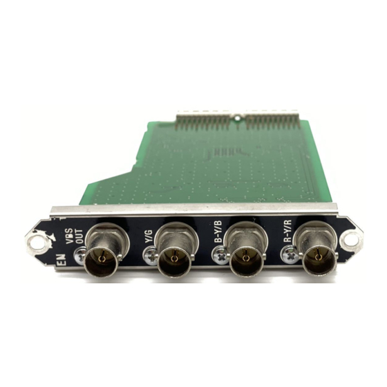
Page 15: Sd エンコーダーユニット Hkcu-951 (別売り
HKCU-951 エンコーダーユニット フレームレートコンバーターユニッ (別売り) ト HKCU-953 (別売り) 拡張スロッ ト に取り付けます。 DIF基板 (SD信号出力端子部) および内部RC基板を拡張スロ ッ ト側に移動して、空いたスロ ッ ト にHKCU-953を取り付けます。 ◆ 取り付けについては、 ソニーのサービス担当者または営業担当者にお 問い合わせく ださい。 ◆ 取り付けについては、 ソニーのサービス担当者または営業担当者にお 問い合わせく ださい。 ご注意 各端子は、 フ ィ ール ド周波数59.94/50 Hzでシステムが動作してい コネクターパネル( 基板) る と きは機能しますが、 フ ィ ール ド周波数60Hzのと きは機能しませ ん。... -
Page 16: 内部スイッチと内部基板
各部の名称と働き 基板 内部スイッチと内部基板 内部スイッチ 下記の内部スイ ッチは、 フロン トパネルを開いたセッ ト内側にあ り ま す。 POWER インジケーター POWER /1.001 インジケーター /1.001 インジケーター REFERENCE 1 内部主電源スイッチ REF IN REFERENCE インジケーターと LOCK スイッチ H PHASE STEP H PHASE 選択スイッチ COARSE POWER CABLE ALARM DELAY OPEN MAIN SHORT INCOM... - Page 17 MIC AMP GAIN (マイクアンプゲイン) 選択スイッチ 基板 カメ ラに接続されるマイ ク (MIC1およびMIC2) の感度に応じて適 正な音量が得られるよう に、 カメ ラ側のアンプゲイ ンを調整します。 本機後面の MIC REMOTE 端子に何も接続されていないか、接 続されていた場合は内部設定 (8ピンと15ピンがHighレベル) に なっている ときに有効です。 POWER インジケーター POWER NORM(60 dB)〜MIN(20 dB)の範囲で、 10 dBステップで調整で INTERCOM PGM1 PGM1/MIX/PGM2 スイッチ きます。 PGM2 PGM1 LEVEL PGM1 つまみ LEVEL PGM2 LEVEL PGM2 つまみ...
- Page 18 各部の名称と働き RETURN SET (リターンビデオ設定) スイッチ 基板 本機の RET1〜 RET3 端子に接続する リ ターンビデオ信号の種類 を選択します。 :HD-SDI 信号 (ローカル設定) (リモー ト) : マス ターセッ ト アップユニッ トMSU-700A/750で 選択した信号 POWER POWER インジケーター :SD信号 (ローカル設定) 。 SD-SDIとVBSの切り換えは、 基 信号フォーマットインジケーター 板内部のスイ ッチで行います。 ◆ 設定方法については、 ソニーのサービス担当者または営業担当者にお 3 ダウンコンバーター 問い合わせく...
- Page 19 6 エッジクロップ位置調整スイッチ HKCU-953 基板(別売リ 内部基板) エッ ジクロ ップ切り出し位置を調整します。 スイ ッチをRIGHT側に押すと右方向 ( ) に、 LEFT側に押すと 左方向 ( ) に移動します。 本スイ ッチは、手を放すと元の位置に戻るモメ ンタ リ ースイ ッチで す。押している間だけ位置が変化します。 POWER インジケーター POWER CONVERT インジケーター CONVERT HKCU-951 基板 (別売リ 内部基板) FRAME REF IN FRAME インジケーター LOCK POWER インジケーター...
- Page 20 仕 様 仕様 HDCU-950 設置環境 • 高温の部屋や熱源の近く は避ける こ と。 一般 • 強電界や強磁界の場所に置かないこ と。 • 乾燥した通風の良い場所である こ と。 電源 AC 100 〜 240 V、 50/60 Hz • 太陽光線、強力ライ ト などが直接あたる場所は避ける こ と。 消費電流 最大 3.6 A 待機電力 約 5 W 動作温度 − 10℃〜+ 40℃ 入出力端子...
- Page 21 出力端子 関連機器 XLR 3ピン、オス(2)、 0 dBu/− 20 dBu HDカラービデオカメ ラ HDC-950/930 HD SDI OUT BNC 型(2)、 SMPTE 292M、 0.8 Vp-p、 HD エレク ト ロニッ ク ビューフ ァイ ンダーHDVF-C700W 75 Ω、 1.485 Gbps/1.4835 Gbps HD エレク ト ロニッ ク ビューフ ァイ ンダーHDVF-20A SD SDI OUT BNC 型(2)、 SMPTE 259M、 0.8 Vp-p、 大型レンズアダプターCA-905L 75 Ω、 270 Mbps ビューフ...
-
Page 22: Hkcu-951(別売り
仕様 HKCU-951 HKCU-953 (別売り) (別売り) 一般 一般 消費電力 5.5 W 消費電力 6.5 W 動作温度 − 10℃〜+ 40℃ 動作温度 −10℃〜+ 40℃ 保存温度 − 20℃〜+ 50℃ 保存温度 −20℃〜+ 50℃ 外形寸法 (幅×高さ×奥行き) 外形寸法 (幅×高さ×奥行き) EN-145 基板: 約 18 ×110×250 mm FC-88 基板: 約 18 ×110×250 mm VDA-61(コネク ターパネル): SDI-73(コネク ターパネル): 約 20 ×92.5 ×140 mm 約 20 ×92.5 ×140 mm 質量... - Page 23 English WARNING: Using this unit at a voltage other than 120 V WARNING may require the use of a different line cord or attachment plug, or both. To reduce the risk of To prevent fire or shock hazard, do not fire or electric shock, refer servicing to qualified expose the unit to rain or moisture.
- Page 24 You are cautioned that any changes or modifications not expressly approved in this manual could void your authority to operate this equipment. The shielded interface cable recommended in this manual must be used with this equipment in order to comply with the limits for a digital device pursuant to Subpart B of Part 15 of This camera control unit is classified as a CLASS 1 LASER FCC Rules.
- Page 25 HKCU-951 SD Encoder Unit (Optional) ........12(E) HKCU-953 HD Frame Rate Converter Unit (Optional) ....12(E) Internal Switches and Internal Boards........... 13(E) Specifications ..................17(E) HDCU-950 ..................17(E) HKCU-951 (Optional) ..............19(E) HKCU-953 (Optional) ..............19(E) Manuals for the HDC-900-series camera system...
-
Page 26: Overview
Interface) signal outputs (2 regular outputs and 1 monitor output) and two SD component SDI signal The HDCU-950 can be connected to a camera using an outputs. Adding the optional units allows the optical fiber cable (two single-mode optical fiber lines,... - Page 27 The results of the HDCU-950 self-diagnosis can be obtained with a text display imposed to the monitor output. Rack mountable By using the optional RMM-301 Rack Mount Adaptor, the HDCU-950 can be installed in a standard EIA 19- inch rack (three units high). 5(E)
-
Page 28: Example System Configuration
POWER CABLE ALRAM OPEN MAIN SHORT INCOM PROD PRIV HDC-950/930 HD Color Video HDCU-950 Camera HD Camera Control Unit + CA-905L Large Lens Adaptor + BKP-9057 Viewfinder Saddle + HDVF-C700W HD Electronic Viewfinder Camera Control Unit 2 Camera 2 POWER... -
Page 29: Sd Signal System
KNEE DETAIL GAMMA SATURATION POWER CABLE WHITE ALRAM FUNCTION OPEN MAIN SHORT BLACK MAINTE NANCE INCOM PROD PRIV SCENE AUTO IRIS/MB ACTIVE MASTER IRIS BLACK PAINT IRIS ALARM REMOTE CONTROL UNIT HDC-950/930 +HDVF-20A HDCU-950 + RM-B750 Remote Control Unit 7(E) -
Page 30: Front Panel
The switch turns on or off the power to the entire only between the HDCU-950 and the connected system, consisting of the HDCU-950, a video camera, camera. an RCP-700-series Remote Control Panel connected ENG (engineer): Engineer line via the REMOTE connector, etc. -
Page 31: Rear Panel
(Factory setting: SD composite sync) The input signal is output from the other connector as- For information on the signal selection, contact a Sony is (loop-through output). If loop-through output is not service or sales representative. used, terminate the unused connector with 75 ohms. - Page 32 3 is made using the camera’s return video switch. The type of input signal can be any of HD-SDI, SD- For details on the assignment, contact a Sony service or sales representative. component SDI, or analog VBS, and can be set using...
- Page 33 Unit, CNU-500/700 Camera Command Network Unit, information. or RCP-700-series Remote Control Panel via a CCA-5 For information on the setting, contact a Sony service or Connection Cable. Control signals are sent and sales representative. received via this connector. When using an RCP-700- series unit, power is also supplied.
-
Page 34: Hkcu-951 Sd Encoder Unit (Optional)
EN connector for pulldown. board. (Factory setting: G, B, R) For information on the setting, contact a Sony service or sales representative. 12(E) -
Page 35: Internal Switches And Internal Boards
AT board Internal Switches and Internal Boards Internal switches The following switches are located inside the unit 1 POWER indicator POWER behind the front panel: 2 /1.001 indicator /1.001 3 90H indicator REFERENCE REF IN 1 Internal main power switch 4 REFERENCE indicators and switch LOCK H PHASE... - Page 36 Locations and Functions of Parts 7 MIC AMP GAIN (microphone amplifier gain) AVP board controls These controls permit you to adjust the amplifier gain of the camera so that the proper audio levels can be obtained appropriate to the sensitivities of the microphones (MIC1 and MIC2) connected to the camera.
- Page 37 RC board 750 Master Setup Unit SD: SD signal (local setting). Switching between SD SDI and VBS is made with an internal switch. For information on the setting, contact a Sony service or sales representative. 1 POWER indicator POWER DRX board...
- Page 38 Locations and Functions of Parts 4 Down-converter mode switch 3 COMPONENT controls To select the operating mode of the down converter: Each is for adjusting the corresponding component SQ: Squeeze mode video output (R/R–Y, G/Y, or B/B–Y). LB: Letterbox mode EC: Edge-Crop mode 4 SC PHASE switch Used to adjust the SC phase with respect to the...
- Page 39 Specifications Dimensions HDCU-950 Unit: mm (inches) General Power supply 100 to 240 V AC, 50/60 Hz Current consumption 3.6 A max. Standby power Approx. 5 W Peak inrush current (1) Power ON, current probe method: 30A (240V), 8A (100V) (2) Hot switching inrush current,...
- Page 40 Specifications Operation manual (1) Input connectors Installation and maintenance manual (1) AC IN 100 to 240 V AC RET 1/2/3 BNC type (3), Optional accessories VBS: 1.0 Vp-p, 75 ohms HD-SDI: SMPTE-292M, AC power cord: 1.485 Gbps/1.4835 Gbps USA and Canada: 1-551-812-XX SD-SDI: SMPTE-259M, 270 Mbps Other countries: 1-782-929-XX REFERENCE...
-
Page 41: Hkcu-951 (Optional)
HKCU-951 (Optional) HKCU-953 (Optional) General General Power consumption Power consumption 5.5 W 6.5 W Operating temperature Operating temperature –10°C to +40°C (+14°F to +104°F) –10°C to +40°C (+14°F to +104°F) Storage temperature Storage temperature –20°C to +50°C (–4°F to +122°F) –20°C to +50°C (–4°F to +122°F) Dimensions (w/h/d) Dimensions (w/h/d) - Page 43 The material contained in this manual consists of information that is the property of Sony Corporation and is intended solely for use by the purchasers of the equipment described in this manual. Sony Corporation expressly prohibits the duplication of any...
- Page 44 Sony Corporation HDCU-950/HKCU-951/ Printed in Japan B&P Company HKCU-953 ( SY ) 2003.01.13 2002 3-619-340-02(2)
Need help?
Do you have a question about the HDCU-950 and is the answer not in the manual?
Questions and answers