
Related Manuals for Sony HDCU1700


Summary of Contents for Sony HDCU1700
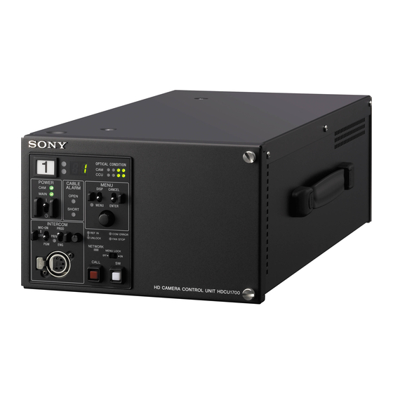
- Page 1 HD CAMERA CONTROL UNIT HDCU1700 4K/HDR PROCESSOR BOARD HKCU2040 3G/HD SDI OUTPUT EXPANSION UNIT HKCU2007 SD ENCODER UNIT HKCU1001 MULTI INTERFACE UNIT HKCU1003 OPERATION MANUAL [English] 1st Edition (Revised 4)
-
Page 2: Table Of Contents
Changing Menu Item Settings ........21 Menu Tree ..............23 Menu List............... 26 Appendix..............39 Notes on Use..............39 Error Messages ............. 39 Specifications............40 HDCU1700 ..............40 HKCU2040 (optional) ............ 41 HKCU2007 (optional) ............ 41 HKCU1001 (optional) ............ 42 HKCU1003 (optional) ............ 42... -
Page 3: Overview
• SD analog composite signal (NTSC/PAL) output, SD picture monitor signal output, SD waveform monitor signal output The HDCU1700 Camera Control Unit is connected to a Sony External reference signals HDC1700 high-definition video camera. It carries out signal The HDCU1700 can be locked to an external reference signal. - Page 4 The camera’s microphone volume can be controlled via the MIC REMOTE connector, MSU, or RCP. Character monitor signal output The results of the HDCU1700 self-diagnosis and setup menu can be obtained with a text display by character signal output. Rack mountable This unit may be installed in a standard EIA 19-inch rack (three units high).
-
Page 5: System Configuration
MSU-1000 series Master Setup Unit Remote Control Panel LAN cable LAN cable Camera Control Unit Camera Optical fiber cable HDC1700 HD Color Video HDCU1700 Camera HD Camera Control Unit HDVF-EL20/EL30 HD Electronic Viewfinder Camera Control Unit Camera Optical fiber cable... -
Page 6: System Operation Example
System Operation Example Image monitor HD-SDI Video monitor HDC1700 LCD monitor LAN cable LAN cable HDCU1700 MSU-1000 series HD-SDI HDC1700 HDCU1700 CCA-5 cable RCP-1000 series CCA-5 cable... -
Page 7: Locations And Functions Of Parts
Locations and Functions of Parts Front Panel a Red tally indicator e Optical signal reception status indicator Lights in red when this unit receives a red tally signal. When This indicates the camera and CCU’s optical signal reception the CALL button on the MSU-1000 series Master Setup Unit, status when performing optical transmissions. - Page 8 To use a headset with a plug other than an XLR 5-pin plug, change menu settings. Pressing the CONTROL knob consult a Sony service or sales representative. performs the same function as setting the CANCEL/ENTER lever to the ENTER position.
-
Page 9: Rear Panel
MSU-1000 series Master Setup Unit. For details on installation, contact a Sony service or sales representative. For details on the setup menu, contact a Sony service or sales representative. b HD/SD SDI OUTPUT (SDI output connectors) area... - Page 10 • The input signal may be set to HD-SDI, SD-SDI, or analog VBS, using the setup menu, or using the MSU-1000 series Master Setup Unit. For details on the setup menu, contact a Sony service or sales representative. Refer also to the Master Setup Unit manual.
-
Page 11: Internal Switches
Quad Link 3G-SDI signal increases by one or four 12G-SDI Expansion Unit (optional) signals as 4K outputs, or four HD outputs. For details on installation, contact a Sony service or sales Note representative. To reduce the risk of electric shock, fire or injury, do not open the cabinet. -
Page 12: Hkcu1001 Sd Encoder Unit (Optional)
HDCU1700’s expansion slots. The format of SDI signals output via each upper/lower pair of VDA-A connectors on the HIF board can be set. For details on installation, contact a Sony service or sales representative. HIF-57 Board SDI OUT a VBS 1, 2 (composite video output 1, 2) connectors... - Page 13 EN-B board in the corresponding expansion slot on VDA-B FRAME the front of the HDCU1700. When either the VDA-A board or REF IN the VDA-B board is installed, you can insert the VDA-C board in an expansion slot on the rear panel of the HDCU1700.
- Page 14 a VBS (composite video signal output) connector (BNC- type) The signal from the video camera may be output as an analog composite signal. b R/R-Y, G/Y, B/B-Y (component video signal output) connectors (BNC-type) The signal from the video camera may be output as a R/R-Y, G/Y, B/B-Y component signal or an RGB component signal.
-
Page 15: Connections And Settings
LOCK RET CTRL FRONT MIC AES/EBU TEST OUT LINE LINE +48V +48V TEST AUDIO IN DC IN 10.5-17V MONI HDCU1700 Prompter/ SDI OUT 3 Floor monitor RET 1-3 (SLOT2) Network cable Monitor (HD-SDI) Switcher (HD-SDI) RET (SD-SDI/HD-SDI) RET (SD-SDI/HD-SDI) MSU-1000/1500... -
Page 16: 4K/Hdr Output System
/GEN LOCK RET CTRL FRONT MIC AES/EBU LINE LINE +48V +48V TEST AUDIO IN DC IN 10.5-17V MONI HDCU1700 RET 1-3 Network cable Switcher Monitor (3G-SDI Quad (3G-SDI Quad Link) Link) RET (SD-SDI/HD-SDI) RET (SD-SDI/HD-SDI) MSU-1000/1500 RET (SD-SDI/HD-SDI) Master Setup Unit... -
Page 17: Status Display
Camera settings Status Display Page 1 The CCU system status can be monitored using a picture monitor connected to the PIX output. 1/ 2 00 0 OF F For information on monitoring and changing settings, see “Setup Menu” on page 21. Displaying the Status Screen The status screen is controlled using the knob and levers in N D: 1 F :4 .7 EX... - Page 18 BLK: Black balance R/G/B/Master value CCU hardware diagnostics BLK γ: Black gamma value FLR: Flare balance R/G/B/Master value 2/1 7 DTL: Detail level Page 3 ** Dia gno si s * * A: AT B: AV P 2:D RX S D Mat rix: ON C: DT X 3:R C C C Red uction: ON...
- Page 19 Page 3 Page 3 * S y ste m Diag 3/3* 5/ 17 *Ne two rk Di ag 3/3 * 8/1 7 I n t erc om C CU System IP Add r : 19 2.1 68. 0 .10 1 Net Mas k : 25 5.2 55.
- Page 20 CCU DTX board diagnostics 3 & 4: Output format of Output 3 & 4 HD CB: The output color bar signal * D T X D iag* 1 1/ 17 Status: SDI output status of each connector Front: Status of power supply to the board installed in option slot 2 and the board name R e t urn Delay :F/S...
-
Page 21: Setup Menu
ROM version information for major Setup Menu components * R O M V e r s i o n * 1 7 / 1 7 C A M E R A H D C 1 7 0 0 The CCU system and peripheral settings can be checked and 1 . - Page 22 The pointer (,) changes to a flashing question mark (?). Turn the CONTROL knob to move the cursor to the desired character, then press the CONTROL knob. Flashing Repeat steps 1 and 2 to enter other characters. • Select INS to insert a space character at the cursor position.
-
Page 23: Menu Tree
Menu Tree SYSTEM OPERATION menu 3D SETTINGS 3D MODE OUTPUT SELECT OUTPUT (S09) 3D OUTPUT (S01) 3D MONITOR POSITION GENLOCK PHASE CONTROL MIX CHROMA REFERENCE (S02) DIFF MODE GENLOCK V SPLIT MODE H STEP BORDER LINE COARSE CHANNEL ID SC PHASE 4K/HDR HDR MODE V PHASE... - Page 24 CCU CONFIGURATION menu PROMPT/TRUNK 1 PROMPTER CH TRUNK LINE (C10) COLOR BAR 4K/HD-BAR (C01) MF CB RATE SLOPE VIDEO SETUP SETUP SD-BAR (C11) SD BLK CLP 2SI DIA MARKER Q FILTER BAR-CHARA G/Y SYNC GRAY VCS RELAY MOVING SYMBOL VIDEO ADJUST 1 TYPE (C12) LEVEL...
- Page 25 NETWORK SETTINGS menu IP ADDR SET HOST IP ADDRESS (N01) SUB NET MASK DEFAU LT GATEWAY LAN SETTINGS AUTO NEGOTIATION (N02) AUTO MDIX CONNECT CONFIGURATION CONNECT SPEED DUPLEX MODE MDI/MDIX SELECT LINK CONDITION CNS MODE CNS SETTINGS MCS MODE (N03) CCU NO MASTER IP ADDRESS NETWORK RESET...
-
Page 26: Menu List
Menu List Note The following conventions are used in the menu list table. Settings column values (e.g. ON, OFF, 0): Default settings Execute via ENTER: Press the CONTROL knob or move the CANCEL/ENTER lever to the ENTER position to execute. SYSTEM OPERATION menu SYSTEM OPERATION Page name... - Page 27 SYSTEM OPERATION Page name Item Settings Description Page No. <MULTI FORMAT> FREQUENCY 1.001, 1.000 Selects the operating frequency. (525NTSC), (625PAL) Notes CAMERA FORMAT When FREQUENCY is set to Selects the transmission format. • FREQUENCY or 1.001: 1080/59.94I, 1080/ CAMERA FORMAT 29.97PsF, 1080/23.98PsF, 720/ Note mode setting changes...
- Page 28 * Use the charts on the following as an example of how to configure these settings. The settings differ depending on the boards connected to the expansion slots. 1080/59.94I 1080/29.97PsF 1080/23.98PsF 720/59.94P 1080/59.94P(4K/HDR) Slot2 1&2 1080/59.94I 1080/29.97PsF 1080/59.94I 720/59.94P 4K/59.94P(2SI) OETF: HLG_Live COLOR: BT.2020 Slot2 3&4 M1080/59.94I...
- Page 29 SYSTEM OPERATION Page name Item Settings Description Page No. <SD ASPECT> SD ASPECT SQUEEZE, EDGE CROP, LETTER Selects the SD output aspect. SD LB SEL 16:9, 15:9, 14:9, 13:9 Selects the LETTER BOX aspect ratio. H-POSITION –99 to 99, (–99) to (99), 0 Sets the horizontal position.
- Page 30 SYSTEM OPERATION Page name Item Settings Description Page No. <RETURN SETUP> FRAME SYNCHRO OFF, ON Set the FRAME SYNCHRO function for the return signal to on/off. RETURN BUFFER NORMAL, EXTEND Set the buffer extension function for the return signal to on/off. SD-RETURN MATRIX OFF, ON...
- Page 31 CCU CONFIGURATION menu CONFIGURATION Page name Item Settings Description Page No. <COLOR BAR> 4K/HD-BAR BAR 16:9 (100%), BAR 16:9 Sets an HD output color bar. (75%), SMPTE 16:9 (BLACK), SMPTE 16:9 (–I/Q), BAR 4:3 (100%), BAR 4:3 (75%), SMPTE 4:3 (BLACK), SMPTE 4:3 (–I/Q), MF-ARIB (75%), MF-ARIB (100%), MF-ARIB (+I), MF-SMPTE (–I,Q), MF-SMPTE (75%,Q), MF-SMPTE...
- Page 32 CONFIGURATION Page name Item Settings Description Page No. 4K 2SI diamond marks This function is for displaying a test pattern like the following in the area at the bottom right of the 4K color bar when 4K 2 sample interleave output. OK is displayed if the connections for Links 1 to 4 are correct, and OK is not displayed if they are incorrect.
- Page 33 CONFIGURATION Page name Item Settings Description Page No. <MONITOR 2> LEVEL GATE ---, 1&2, 1, 2, OFF 1&2: Displays level gate 1 & 2. 1: Displays level gate 1. 2: Displays level gate 2. ---: Displayed when camera not connected, video output not set to CAMERA, or video output is set to CAMERA and GATE MARKER is ON.
- Page 34 CONFIGURATION Page name Item Settings Description Page No. <INTERCOM> INTERCOM CH 1CH, 2CH Selects the intercom channel number. SYSTEM INTERFACE PRODUCER 4WIRE, RTS, CLEAR COM Sets the producer line intercom system. CANCEL LVL –99 to 99, 0 Sets the side tone cancel level. Connects to a 200 Ω...
- Page 35 CONFIGURATION Page name Item Settings Description Page No. <VIDEO SETUP> SETUP ON, OFF, --- ON: Adds a setup signal to VBS and SD YCD component signal Ych-SYNC. OFF: No setup signal is added. ---: Displayed when the format is PAL. (Display only) SD BLK CLP OFF, ON Y signals from SD SDI output that are less than 0%...
- Page 36 CONFIGURATION Page name Item Settings Description Page No. <DISPLAY> MESSAGE ALL, WARNING, OFF ALL: Displays all messages. WARNING: Displays system warning messages and menu control messages. Turn camera messages OFF: Displays only menu control messages. and switch settings ON/ MASTER GAIN ON, OFF Displays or hides the master gain indication.
- Page 37 CONFIGURATION Page name Item Settings Description Page No. <OTHERS> ASSIGNABLE NONE, BARS, CLEAN, CAM Sets the function for the assignable button. POWER, FORCE LEGACY, REF NONE: No assignment. LOCAL HD, REF LOCAL SD BARS: Sets the color bar output to ON/OFF. CLEAN: Sets character superimposition for all output slots to ON/OFF.
- Page 38 NETWORK SETTINGS menu NETWORK SETTINGS Page name Item Settings Description Page No. <IP ADDR SET> HOST IP ADDRESS 0.0.0.0 to 255.255.255.255 Displays the IP address. SUB NET MASK 0.0.0.0 to 255.255.255.254 Displays the subnet mask. DEFAULT GATEWAY 0.0.0.0 to 255.255.255.255 Displays the default gateway.
-
Page 39: Appendix
Error Messages Appendix When an error is detected in this unit or the camera, the ALARM indicator turns on and an error message is displayed on this unit. Notes on Use Error message Indication CCU:GEN LOCK NG External reference sync error Use and storage locations CCU:DRX NG Front DRX board power supply,... -
Page 40: Specifications
Specifications CAMERA Optical fiber connector (1) 180 V DC power supply INTERCOM/TALLY/ D-sub 25-pin connector (1) • INTERCOM (PROD/ENG), 4W/RTS/CC, HDCU1700 0 dBu • PGM, 2 systems, 0 dBu/–20 dBu • TALLY (R, G, Y) General • FLAG Power supply... -
Page 41: Hkcu2040 (Optional)
Supplied accessories Output connectors Number plates (1 set) DIF board Operation guide (1) SDI OUT BNC-type (4) 12G-SDI: SMPTE ST2082, 0.8 Vp-p, Operation manual (CD-ROM) (1) 75 ohms, 11.880 Gbps/11.868 Gbps Optional accessories 3G-SDI: SMPTE ST424/ST425, 0.8 Vp-p, AC power cord: 75 ohms, 2.970 Gbps/2.967 Gbps USA and Canada: 1-551-812-XX HD-SDI: SMPTE ST292, 0.8 Vp-p,... -
Page 42: Hkcu1001 (Optional)
BNC-type (1), VBS/R/G/B (VBS 1.0 Vp-p, Note 75 ohms) Always verify that the unit is operating properly before use. SONY WILL NOT BE LIABLE FOR DAMAGES OF ANY WF OUT BNC-type (1), VBS/R/G/B/SEQ (VBS 1.0 Vp-p, 75 ohms) KIND INCLUDING, BUT NOT LIMITED TO,... - Page 43 Sony Corporation HDCU1700 (SY) 4-439-357-05(1) © 2012...
Need help?
Do you have a question about the HDCU1700 and is the answer not in the manual?
Questions and answers